P 15/ 25
 Repair
[3] DISASSEMBLY/ASSEMBLY
[3]-6. Impact bolt in Torque limiter section (cont.)
ASSEMBLING
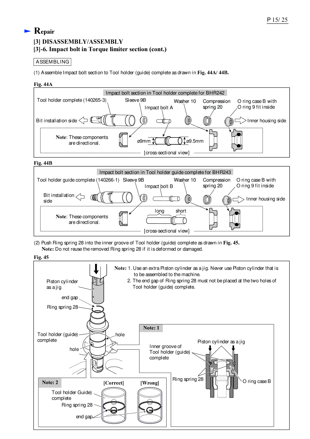
(1) Assemble Impact bolt section to Tool holder (guide) complete as drawn in Fig. 44A/ 44B.
Fig. 44A
Impact bolt section in Tool holder complete for BHR242
Tool holder complete
Bit installation side ![]()
![]()
![]()
![]()
![]()
![]()
![]()
![]()
Note: These components are directional.
Sleeve 9B | Washer 10 Compression | O ring case B with |
Impact bolt A | spring 20 | O ring 9 fit inside |
|
| Inner housing side |
ø9mm ![]()
![]()
![]() ø9.5mm
ø9.5mm
Fig. 44B
Impact bolt section in Tool holder guide complete for BHR243
Tool holder guide complete | Washer 10 |
Impact bolt B
Bit installation side
![]()
![]()
![]()
![]()
![]()
![]()
![]()
![]()
![]() long short Note: These components
long short Note: These components ![]()
![]()
![]()
are directional. ![]()
![]()
Compression | O ring case B with |
spring 20 | O ring 9 fit inside |
| Inner housing side |
(2)Push Ring spring 28 into the inner groove of Tool holder (guide) complete as drawn in Fig. 45. Note: Do not reuse the removed Ring spring 28 if it is deformed or damaged.
Fig. 45
|
|
| Note: 1. Use an extra Piston cylinder as a jig. Never use Piston cylinder that is |
|
|
| |
|
|
| to be assembled to the machine. |
Piston cylinder |
|
| 2. The end gap of Ring spring 28 must not be placed at the two holes of |
|
| ||
as a jig |
|
| Tool holder (guide) complete. |
end gap ![]() Ring spring 28
Ring spring 28![]()
![]()
![]()
Tool holder (guide) | Note: 1 | |
hole | ||
complete | Piston cylinder as a jig | |
hole | Inner groove of | |
Tool holder (guide) | ||
| ||
| complete |
Note: 2 | [Correct] | [Wrong] | Ring spring 28 | O ring case B |
| ||||
Tool holder Guide) |
|
|
|
|
complete |
|
|
|
|
Ring spring 28 |
|
|
|
|
end gap |
|
|
|
|