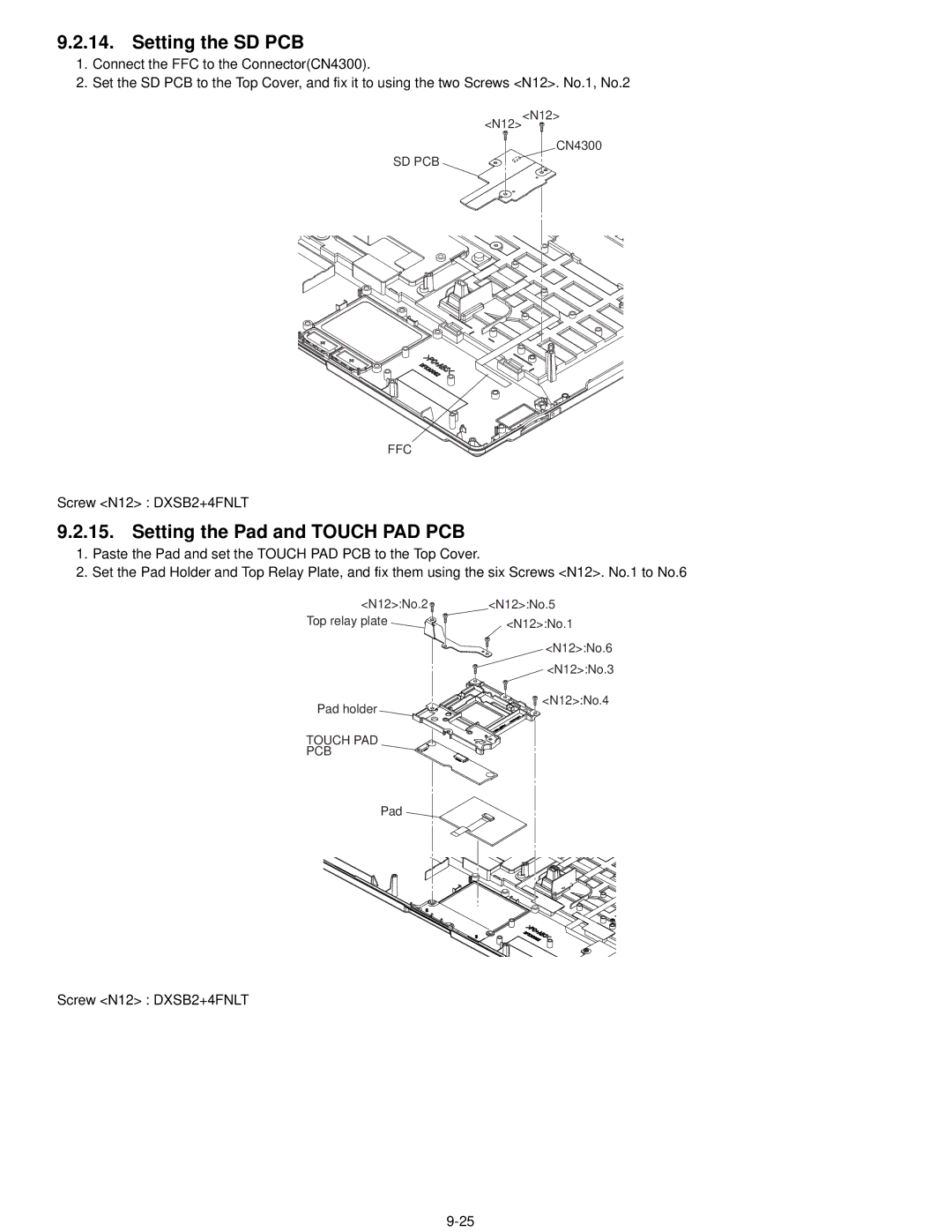
9.2.14. Setting the SD PCB
1.Connect the FFC to the Connector(CN4300).
2.Set the SD PCB to the Top Cover, and fix it to using the two Screws <N12>. No.1, No.2
<N12><N12>
CN4300
SD PCB
FFC
Screw <N12> : DXSB2+4FNLT
9.2.15. Setting the Pad and TOUCH PAD PCB
1.Paste the Pad and set the TOUCH PAD PCB to the Top Cover.
2.Set the Pad Holder and Top Relay Plate, and fix them using the six Screws <N12>. No.1 to No.6
<N12>:No.2 | <N12>:No.5 |
Top relay plate | <N12>:No.1 |
| <N12>:No.6 |
| <N12>:No.3 |
Pad holder | <N12>:No.4 |
| |
TOUCH PAD |
|
PCB |
|
Pad |
|
Screw <N12> : DXSB2+4FNLT
