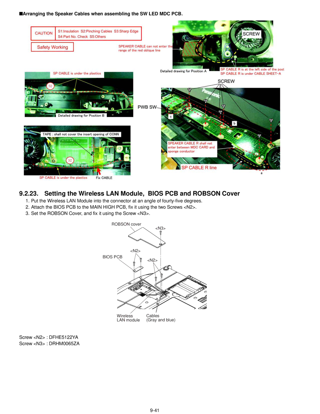
■Arranging the Speaker Cables when assembling the SW LED MDC PCB.
9.2.23. Setting the Wireless LAN Module, BIOS PCB and ROBSON Cover
1.Put the Wireless LAN Module into the connector at an angle of
2.Attach the BIOS PCB to the MAIN HIGH PCB, fix it using the two Screws <N2>.
3.Set the ROBSON Cover, and fix it using the Screw <N3>.
ROBSON cover
<N3>
<N2>
BIOS PCB
<N2>
Wireless | Cables |
LAN module | (Gray and blue) |
Screw <N2> : DFHE5122YA
Screw <N3> : DRHM0065ZA
