Contents
Model No. CF-52AJYZDZM
Page
Laser Safety Information
Page
Page
Contents
To check the model number
Specifications
CD/DVD Drive
Wireless LAN Only for model with wireless LAN
Microphone jack
Names and Functions of Parts
EX PC
UFCBGA
Diagnosis Procedure
Troubleshooting
Power-On Self Test Boot Check
Error Diagnosis by Checking Beep Signal Sound
Outline of Post
Stuck key
02D0 System cache error Cache disabled
Self Diagnosis Test
When you execute an automatic test
Operation of PC-Diagnostic Utility
Selection of tested device
Test Item and Division of trouble
GPS
SW LED MDC PCB
Wiring Connection Diagram
LED PCB
Disassembly/Reassembly
Disassembly Flowchart
PAD PCB PWR Battery
Removing the HDD
Preparation
HDD Mounting Kit
DVD Multi Drive
Removing the Dimm Memory Card
Removing the Robson Cover, Wireless LAN Module and Bios
Bios PCB
Removing the Tilt Panl Ass’y
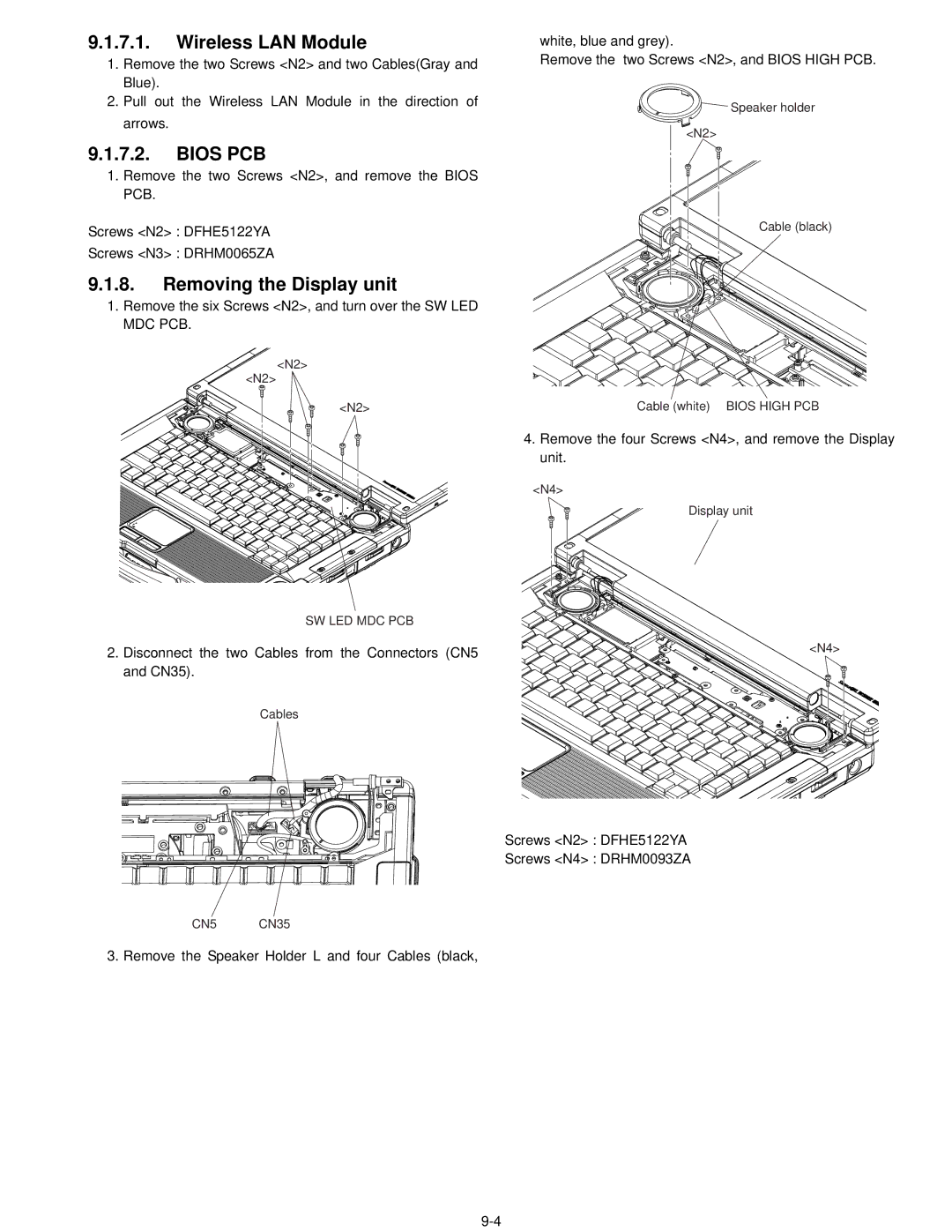
SW LED MDC PCB
Wireless LAN Module
Bios PCB
Removing the Display unit
Antenna
Removing the LCD unit, Inverter Ass’y and Antenna PWB L,R
Removing the Handle Assy
LCD
Removing the Keyboard
Removing the Modem
Speaker R
Speaker L
Removing the Top Cover
Removing the Pad and Touch PAD PCB
Removing the SD PCB
Removing the Audio PCB
Removing the PWR Battery LED PCB
PWR Battery LED PCB Wwan PCB
Removing the Wwan PCB
KBD Earth Plate CN7
Removing the KBD Earth Plate
Removing the Hinge Support R
Removing the Fan Ass’y
Removing the Heat Sink Ass’y
Removing the Battery Connector Ass’y
Removing the Hinge Support L and MP Hold Plate
Removing the SC Relay PCB and HDD Hold Plate
CN4 Main High PCB
Removing the Serial PCB
Removing the Main High PCB
Serial PCB
Setting the Main High PCB
Reassembly Instructions
Setting of Main PCB before assembling
Page
Setting the Heat Sink Ass’y
Setting the Serial PCB
Setting the Fan Ass’y
Page
Setting the SC Relay PCB and HDD Hold Plate
Setting the Hinge Support L and MP Hold Plate
Setting the Battery Connector Ass’y
Setting the Hinge Cover R
KBD Earth Plate
Setting the KBD Earth Plate
PWR Battery LED PCB
Setting the PWR Battery LED PCB
Setting the Audio PCB
Setting the Wwan PCB
Setting the Pad and Touch PAD PCB
Setting the SD PCB
Setting the Top Cover
Setting the Keyboard
Page
Setting the Modem
Setting the Speakers
How to paste the Tape
Setting the Handle Ass’y
Setting the LCD Unit, Inverter Ass’y and Antenna PWB L, R
Shield Sheet B
LCD Damper C
Adhesive Tape B Adhesive Tape a
Tape
Sheet
Page
Setting the Display Unit, Bios High PCB and SW LED MDC PCB
Arranging the Cables when assembling the LCD Unit
Page
Setting the Wireless LAN Module, Bios PCB and Robson Cover
Setting the Tilt Panel Ass’y
Setting the Dimm Memory Card and Dimm Cover
Screw N202 DRSB2+4FKLT
Setting the HDD
Screw tightening torque
Exploded View
CF-52AJYZDZM
DM4
DM1
DM5
DM2 DM7
K14 K26 E16 E16-2
Replacement Parts List
RTL
NRP
Mechanical Parts
DFHR3G78ZA FIN Duct
DFHE1089ZA
DM2
DM3
DM6
EEFCX0D221R
CPU
Chipset PM
Chipset
RESISTOR, 1/16W, 0Ω
EEFCX0J101R
Connector
CONNECTOR, USB
EEFUD0J151ER
IC, Switch
Temperature Sensor
IC, FET Switch
IC, USB Power SW
Inductor
IDUCTOR, Common Mode Filter
Switch
Jack
RESISTOR, 1/16W, 1Ω
RESISTOR, 1/16W, 10KΩ
RESISTOR, 1/16W, 20KΩ
RESISTOR, 1/16W, 3KΩ
Jumper
RESISTOR, 1/16W, 10MΩ
RESISTOR, 1/16W, 47KΩ
RESISTOR, 1/16W, 18KΩ
RESISTOR, 1/16W, 15KΩ
RESISTOR, 1/16W, 33KΩ
RESISTOR, 1/16W, 16KΩ
Audio Codec
IC, Audio Power Amplifier
EVQPLDA15 Switch
ECUV1H103ZFG Inductor
IC, DC/DC Converter
DIP Switch
Bluetooth Module
DEDRB081L20 Diode
Chip Inductor

