DS5001FP
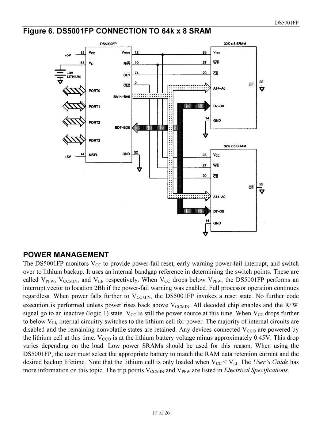
Figure 6. DS5001FP CONNECTION TO 64k x 8 SRAM
POWER MANAGEMENT
The DS5001FP monitors VCC to provide
called VPFW, VCCMIN, and VLI, respectively. When VCC drops below VPFW, the DS5001FP performs an interrupt vector to location 2Bh if the
regardless. When power falls further to VCCMIN, the DS5001FP invokes a reset state. No further code
execution is performed unless power rises back above VCCMIN. All decoded chip enables and the R/ W signal go to an inactive (logic 1) state. VCC is still the power source at this time. When VCC drops further
to below VLI, internal circuitry switches to the lithium cell for power. The majority of internal circuits are disabled and the remaining nonvolatile states are retained. Any devices connected VCCO are powered by the lithium cell at this time. VCCO is at the lithium battery voltage minus approximately 0.45V. This drop varies depending on the load. Low power SRAMs should be used for this reason. When using the DS5001FP, the user must select the appropriate battery to match the RAM data retention current and the desired backup lifetime. Note that the lithium cell is only loaded when VCC < VLI. The User’s Guide has more information on this topic. The trip points VCCMIN and VPFW are listed in Electrical Specifications.
10 of 26