Disassembly Procedures
!WARNING
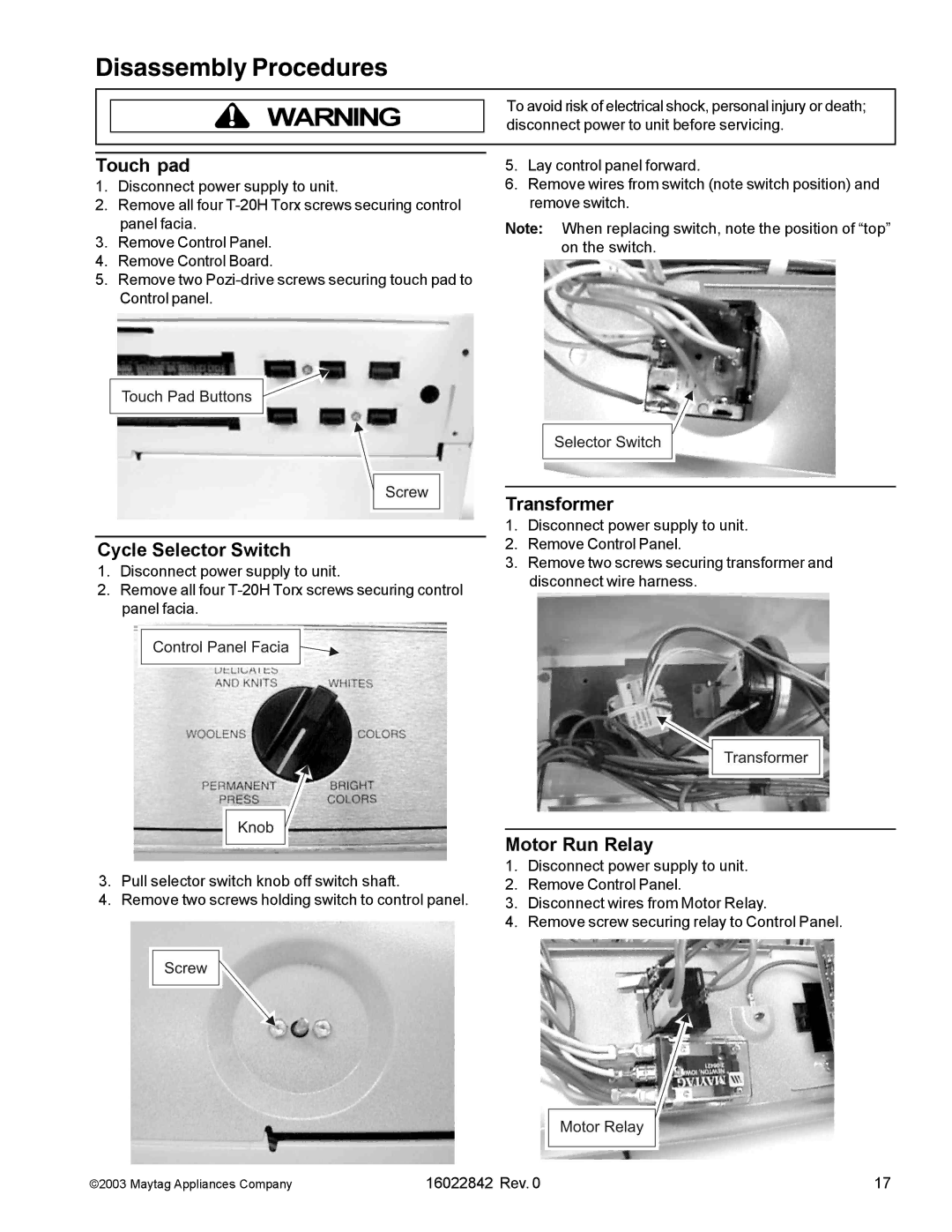
Touch pad
1.Disconnect power supply to unit.
2.Remove all four
3.Remove Control Panel.
4.Remove Control Board.
5.Remove two
Cycle Selector Switch
1.Disconnect power supply to unit.
2.Remove all four
3.Pull selector switch knob off switch shaft.
4.Remove two screws holding switch to control panel.
To avoid risk of electrical shock, personal injury or death; disconnect power to unit before servicing.
5.Lay control panel forward.
6.Remove wires from switch (note switch position) and remove switch.
Note: When replacing switch, note the position of “top” on the switch.
Transformer
1.Disconnect power supply to unit.
2.Remove Control Panel.
3.Remove two screws securing transformer and disconnect wire harness.
Motor Run Relay
1.Disconnect power supply to unit.
2.Remove Control Panel.
3.Disconnect wires from Motor Relay.
4.Remove screw securing relay to Control Panel.
©2003 Maytag Appliances Company | 16022842 Rev. 0 | 17 |
