W10088776A
Secheuse Electrique Avec Conduit Devacuation
Table DES Matieres
Table of Contents Indice
Out Do not use
Dryer Safety
When the dryer is Used Near
Caulking gun
Compound For installing
Installation Clearances
Vent clamps
5cm
Installation Requirements
Mobile Home Installations
110cm
Wirrceptacl lO-30R
If using a power supply cord
If connecting by direct wire
If your outlet looks like this
It is your responsibility
Do not use an extension cord
AB C D
Nema
If your Home has You will Go to Section Connecting to
Wire receptacle Nfma type 14-30R Prong plug
Wire connection Power Supply Cord
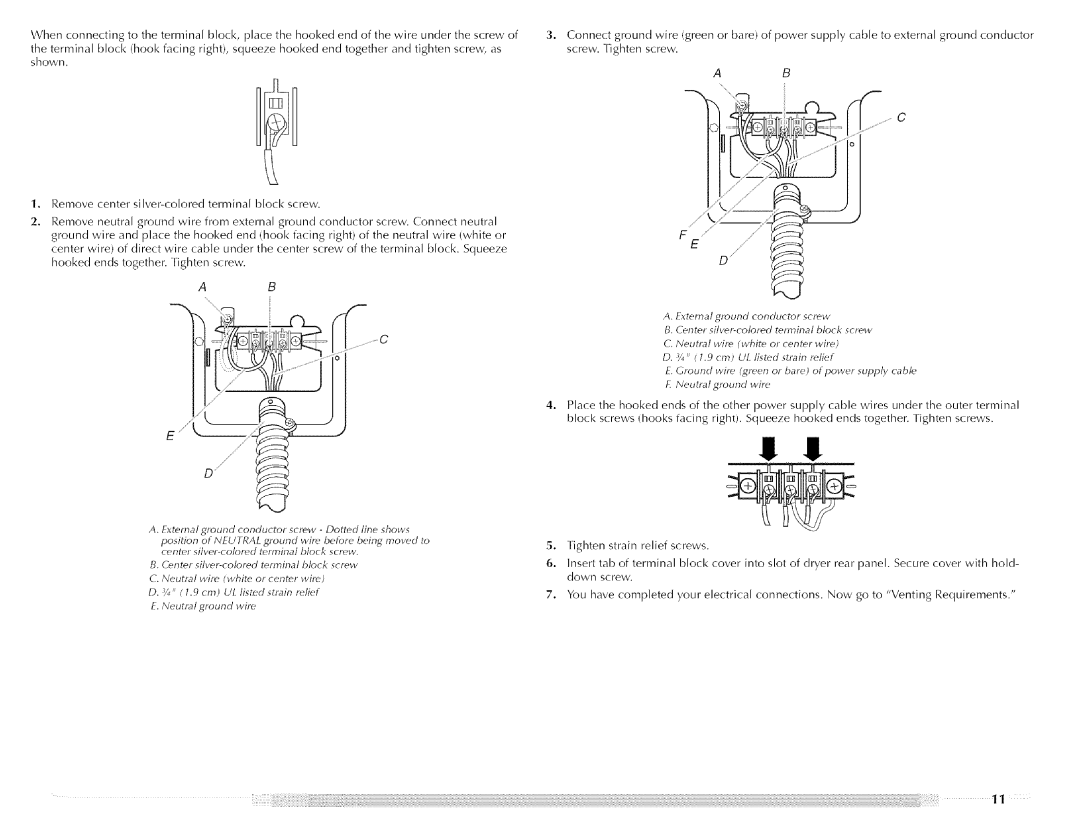
Shown
Wire connection Direct Wire
Neutral ground wire Fxternal ground conductor screw
Elbows
If using awl existing vent system
If this is a new vent system Vent material
Rigid metal vent
Louwred hood styli Box hood style
Recommended exhaust installations
10.2 cm
Vent
Alternate installations for close clearances
Special provisions for mobile home installations
Determine vent path
Check
Vent system chart 0 ft 0 m to 10 ft 3.0 m
No.
Length of flexible metal vent
Canada
U.S.A
To stop your dryer
Dryer USE
Or fire
How Automatic Drying Works
Temp Time
Every Load Cleaning
Dryer Care
Rack Dry
From Inside the Dryer Cabinet
For direct-wired dryers
As Needed Cleaning
Moving care For power supply cord-connected dryers
Do not use a metal foil vent
Troubleshooting
Use a heavy metal vent Do not use a plastic vent
Is the dryer being used for the first time?
Is the dryer located in a closet?
Has an air dry cycle been selected?
Lint on load Is the lint screen clogged?
If you need replacement parts
Ii %iii!i
Maytag Corporation Major Appliance Warranty
Page
Ii%iii!i!27
Seguridad DE LA Secadora
Abrazaderas para ducto
Que
Tijeras para lata instalaciones Del nuevo ducto de escape
Nivel
27%
Patas niveladoras
Piezas necesarias
Espacios para la instalaci6n
Conexi6n elctrica
Ponerse en contacto con un instalador el6ctrico calificado
As instalaciones en casas rodantes necesitan
Cntacto de 3 alambrs f 10-30R
Siempleauncable de suministro el6ctrico
Si el contacto de pared luce como 6ste
Instale el protector de cables
Incendio o choque electrico
Conector Del conducto Removible
IZI¸IZIL
Elctrica
Opciones para la conexi6n
ConductordetierraexternoAprieteeltornillo
£ Hilo neutlo diGpuesta a tiGna
Ld!Y
Si usa un sistema de ventilaci6n existente
Peligro de Incendio
BienMdjor
Ducto descape c/rnetal pesado c/4 10,2 crn
Ducto de escape de metal rigido
10,2 cm
Instalaciones
Flexible
Para espacios limitados Seleccione
De ventilaci6n
Pies 105 pies 90 pies 36,6 m 32,0 m 27,4 m
Peligro de Peso Excesivo
Devueltas
Del ducto
SJ,a¢, oY 6 , 5eaioa
Ciclo de Aire
USO DE LA Secadora
Temp Tiempo
Para detener y volver a poner en marcha
Para volver a poner en marcha su secadora
Estante
Del ducto de escape
Limpieza de cada carga
Limpieza peri6dica
Cuidado para las vacaciones
Demasiado largos, o la carga est demasiado caliente
Solucion DE Problemas
La secadora no funciona
El temporizador no avanza notablemente
EslJ la secadora ubicada en un armario?
Ropa arrugada
Pelusa en la ropa Est obstruido el filtro de pelusa?
Attn CAR Center
Ayuda O Servicio Tecnico
Si necesita piezas de repuesto
Exclusion DE Garantas IMPLiCITAS Limitacin DE Recursos
Garanta Limitada DE UN Aiio
Page
Votre scurit et celle des autres est tres importante
Securite DE LA Secheuse
Utiiisee
Secheuse Les Articles Contamines Par des
Incendie Ou une explosion Fabriques
Iorsque La secheuse
Iid de nivellement
Instructions Dinstallation
Piices fournies
Linstallation dans une maison mobile exige
Dimensions de la scheuse
Cest Iutilisateur quincombe la responsabilit de
Instructions DE Liaison a LA Terre
BonMeilleur
CZmduit dvacuation en mtal Iourd de 4 10,2 cm
Conduit mtallique flexible
Bride deserrage
Installations dvacuation recommandes
Rigide ou souple
Tableau
Autres installations o le dgagement est rduit
Dterminer Iitinraire dacheminement du conduit
Tableaux des systmes dvacuation
Nombre De change Ments de Direction
Du conduit Direction
Dvacuation mtallique
HaH
Si la scheuse ne dmarre pas, vrifier ce qui suit
Us ts, @
Arrt et remise en marche
Fonctionnement du programme de schage automatique
Nettoyage au besoin
Entretien DE LA Secheuse
Nettoyage avant chaque charge
Iintrieur du conduit dvacuation
Precautions prendre avant un dmnagement
O1tHl
Intrieur de la caisse de la scheuse
Ne pas utiliser un conduit devacuation en feuilie de metal
Ne pas utiliser un conduit devacuation en piastique
Charges froiss6es
Charpie sur la charge
Taches sur la charge ou sur le tambour
Pour plus dassistance
Assistance OU Service
Si vous avez besoin de pices de rechange
Garantie Limitce DE UN AN
Garantie DES Gros Appareils Menagers Maytag Corporation
W10088776A