14
Step 12C
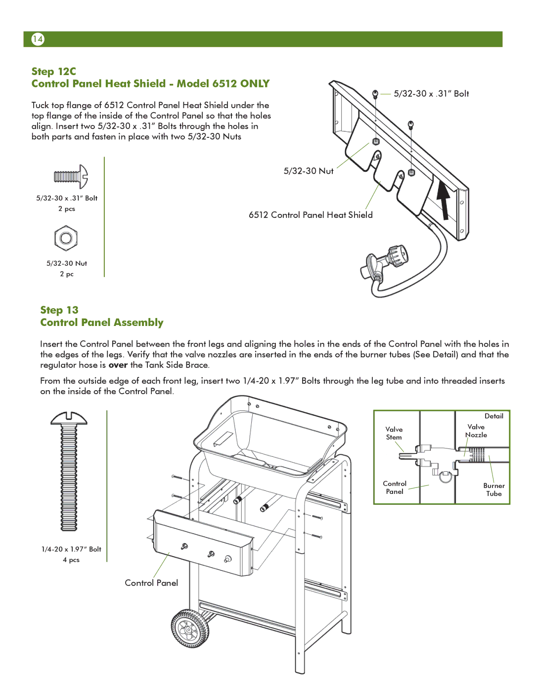
Control Panel Heat Shield - Model 6512 ONLY
Tuck top flange of 6512 Control Panel Heat Shield under the top flange of the inside of the Control Panel so that the holes align. Insert two
2 pcs
6512 Control Panel Heat Shield
2 pc
Step 13
Control Panel Assembly
Insert the Control Panel between the front legs and aligning the holes in the ends of the Control Panel with the holes in the edges of the legs. Verify that the valve nozzles are inserted in the ends of the burner tubes (See Detail) and that the regulator hose is over the Tank Side Brace.
From the outside edge of each front leg, insert two
| Detail | |
Valve | Valve | |
Nozzle | ||
Stem | ||
|
Control | Burner |
Panel | Tube |
4 pcs
Control Panel