8
Step 4
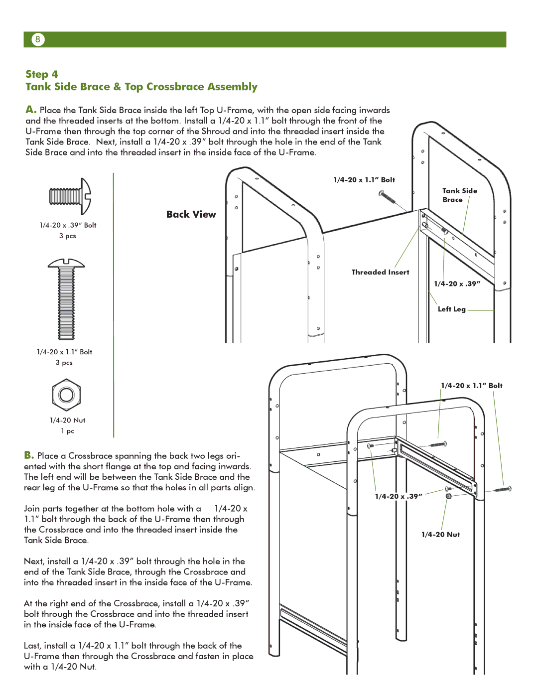
Tank Side Brace & Top Crossbrace Assembly
A.Place the Tank Side Brace inside the left Top
Back View
3 pcs
3 pcs
1pc
B.Place a Crossbrace spanning the back two legs ori- ented with the short flange at the top and facing inwards. The left end will be between the Tank Side Brace and the rear leg of the
Join parts together at the bottom hole with a
Next, install a
At the right end of the Crossbrace, install a
Last, install a
Tank Side
Brace
Threaded Insert
Left Leg