To reduce the risk of a fire beneath the grill:
·Inspect and clean burner/venturi tubes for insects and insect nests.
·Be sure burners are
How to Clean the Burners:
A)Make sure the LP cylinder grill control knobs are turned OFF; and the grill is completely cooled.
B)Carefully remove Cooking Grids and Flame Diffusers.
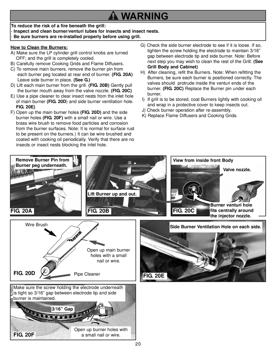
C)To remove main burners, remove the burner pin from each burner peg located at rear end of burner. (FIG. 20A) Leave side burner in place. (See G.)
D)Lift each main burner from the grill. (FIG. 20B) Gently pull the burner mouth away from the valve nozzle. (FIG. 20C)
E)Use a pipe cleaner to clear insect nests from the inlet hole of main burner (FIG. 20D) and side burner ventilation hole.
FIG. 20E)
F)Open up the main burner holes (FIG. 20D) and the side burner holes (FIG. 20F) with a small nail or wire. Use a brass wire brush to remove food particles and corrosion from the burner surfaces. Note: It is normal for surface rust to be present on the burners.) It can be wire brushed and coated with cooking oil periodically. Verify that there are no insects or insect nests blocking the inlet hole.
G)Check the side burner electrode to see if it is loose. If so, tighten the screw holding the electrode to maintain 3/16” gap between electrode tip and side burner. Note: Before next step you may wish to clean the rest of the Grill. (See
Grill Body and Cabinet)
H)After cleaning, refit the Burners. Note: When refitting the Burners, be sure each burner is positioned correctly. The valves should protrude inside the venturi ends of the burner. (FIG. 20C) Replace the Burner pin under each burner.
I)If grill is to be stored, coat Burners lightly with cooking oil and wrap in a protective cover to keep insects out.
J)Check burner operation after
K)Replace Flame Diffusers and Cooking Grids.
|
|
|
|
|
|
|
|
|
|
|
|
|
|
|
|
|
|
|
|
|
|
| Remove Burner Pin from |
|
|
|
|
|
|
|
|
|
|
| View from inside front Body |
| |||||||
| Burner peg underneath. |
|
|
|
|
|
|
|
|
|
|
|
|
|
|
|
|
| |||
|
|
|
|
|
|
|
|
|
|
|
|
|
| Valve nozzle. | |||||||
|
|
|
|
|
|
|
|
|
|
|
|
|
|
|
|
|
| ||||
|
|
|
|
|
|
|
|
|
|
|
|
|
|
|
|
|
| ||||
|
|
|
|
|
|
|
|
|
|
|
|
|
|
|
|
|
|
|
| ||
|
|
|
|
|
|
|
| Lift Burner up and out. |
|
|
|
|
|
|
|
|
|
|
| ||
|
|
|
|
|
|
|
|
|
|
|
|
|
|
|
|
|
|
|
| ||
|
|
|
|
|
|
|
|
|
|
|
|
|
|
|
|
|
| Burner venturi hole | |||
FIG. 20A |
|
|
| FIG. 20B |
|
|
|
|
| FIG. 20C |
| fits centrally around |
| ||||||||
|
|
|
|
|
|
|
|
|
|
|
|
|
|
|
|
|
| the injector nozzle. |
| ||
|
|
|
|
|
|
|
|
|
|
|
|
|
|
|
|
|
| ||||
|
|
|
|
|
|
|
|
|
|
|
|
|
|
|
|
|
|
| |||
|
|
|
|
|
|
|
|
|
|
|
|
|
|
|
|
|
|
|
|
|
|
|
|
|
|
|
|
|
|
|
|
|
|
|
|
|
|
|
|
|
|
|
|
|
| Wire Brush |
|
|
|
|
|
|
|
|
|
| Side Burner Ventilation Hole on each side. |
| |||||||
|
|
|
|
|
|
|
|
|
|
|
|
|
|
| |||||||
|
|
|
|
|
|
|
|
|
|
|
|
|
|
|
|
|
|
|
|
|
|
|
|
|
|
|
|
| Open up main burner |
|
|
|
|
| ||
|
|
|
|
|
|
| holes with a small |
|
|
|
|
| ||
|
|
|
|
|
|
| nail or wire. |
|
|
|
|
| ||
|
|
|
|
|
|
|
|
|
|
|
|
| ||
| FIG. 20D |
|
|
|
|
|
| |||||||
|
|
|
| Pipe Cleaner |
|
|
|
|
|
| ||||
|
|
|
|
|
| FIG. 20E |
| |||||||
|
|
|
|
|
|
|
|
|
|
|
|
|
| |
|
|
|
|
|
|
|
|
|
|
|
|
|
| |
|
|
|
|
|
|
|
|
|
|
|
|
|
|
|
|
|
|
|
|
|
|
|
|
|
|
|
|
|
|
|
|
|
|
|
|
|
|
|
|
| ||||
|
|
|
|
|
|
|
|
|
|
|
|
|
|
|
| Make sure the screw holding the electrode underneath |
|
|
|
|
| ||||||||
| is tight so 3/16” gap between electrode tip and side |
|
|
|
|
| ||||||||
| burner is maintained. |
|
|
|
|
|
|
|
|
|
| |||
|
|
|
|
|
|
|
|
|
|
|
|
|
|
|
|
|
| 3/16” Gap |
|
|
|
|
|
|
|
|
|
| |
| FIG. 20F | Open up burner holes with |
|
|
|
| ||||||||
|
| a small nail or wire. |
|
|
|
| ||||||||
|
|
|
|
|
|
|
|
|
|
|
|
|
|
|
20