To reduce the risk of an injury: The following assembly will require
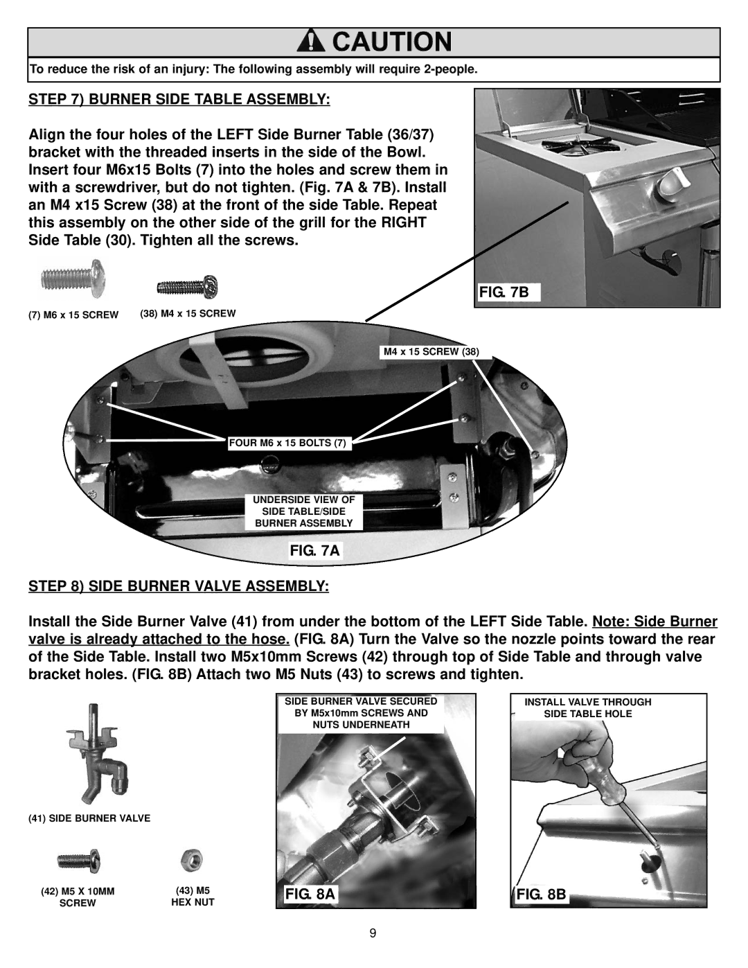
STEP 7) BURNER SIDE TABLE ASSEMBLY:
Align the four holes of the LEFT Side Burner Table (36/37) bracket with the threaded inserts in the side of the Bowl. Insert four M6x15 Bolts (7) into the holes and screw them in with a screwdriver, but do not tighten. (Fig. 7A & 7B). Install an M4 x15 Screw (38) at the front of the side Table. Repeat this assembly on the other side of the grill for the RIGHT Side Table (30). Tighten all the screws.
(7) M6 x 15 SCREW (38) M4 x 15 SCREW
FIG. 7B
M4 x 15 SCREW (38)
![]() FOUR M6 x 15 BOLTS (7)
FOUR M6 x 15 BOLTS (7)
UNDERSIDE VIEW OF
SIDE TABLE/SIDE
BURNER ASSEMBLY
FIG. 7A
STEP 8) SIDE BURNER VALVE ASSEMBLY:
Install the Side Burner Valve (41) from under the bottom of the LEFT Side Table. Note: Side Burner valve is already attached to the hose. (FIG. 8A) Turn the Valve so the nozzle points toward the rear of the Side Table. Install two M5x10mm Screws (42) through top of Side Table and through valve bracket holes. (FIG. 8B) Attach two M5 Nuts (43) to screws and tighten.
SIDE BURNER VALVE SECURED
BY M5x10mm SCREWS AND
NUTS UNDERNEATH
INSTALL VALVE THROUGH
SIDE TABLE HOLE
(41) SIDE BURNER VALVE
(42) M5 X 10MM | (43) M5 |
SCREW | HEX NUT |
FIG. 8A
FIG. 8B
9
