STEP 2) Cart Sides and Bottom Assembly:
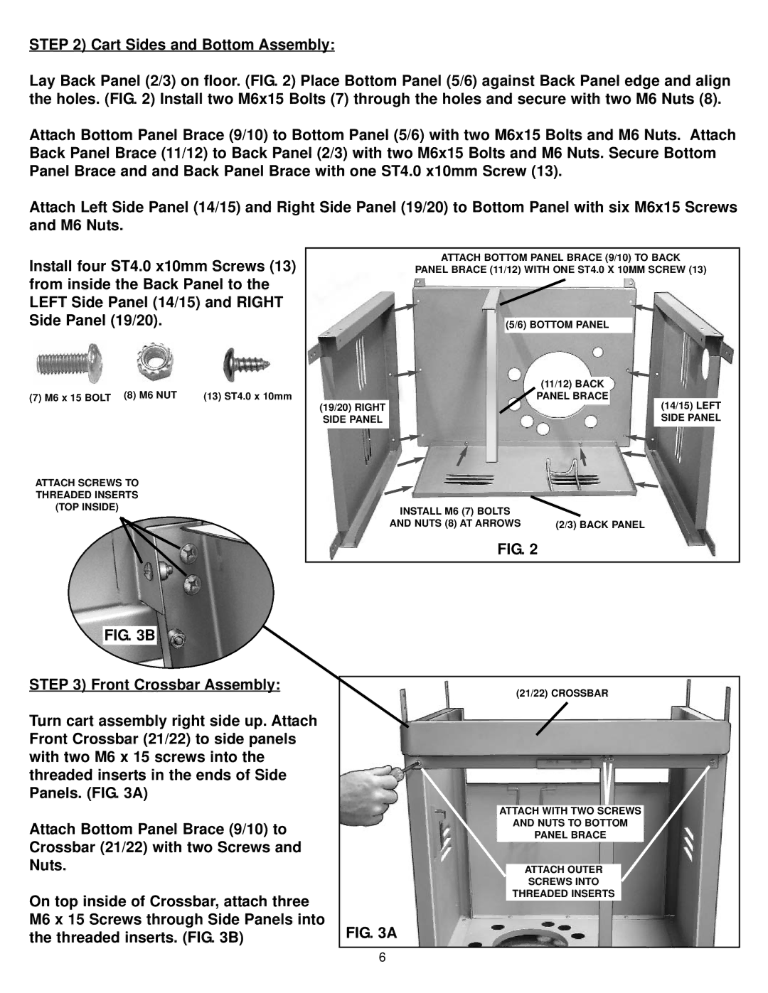
Lay Back Panel (2/3) on floor. (FIG. 2) Place Bottom Panel (5/6) against Back Panel edge and align the holes. (FIG. 2) Install two M6x15 Bolts (7) through the holes and secure with two M6 Nuts (8).
Attach Bottom Panel Brace (9/10) to Bottom Panel (5/6) with two M6x15 Bolts and M6 Nuts. Attach Back Panel Brace (11/12) to Back Panel (2/3) with two M6x15 Bolts and M6 Nuts. Secure Bottom Panel Brace and and Back Panel Brace with one ST4.0 x10mm Screw (13).
Attach Left Side Panel (14/15) and Right Side Panel (19/20) to Bottom Panel with six M6x15 Screws and M6 Nuts.
Install four ST4.0 x10mm Screws (13) from inside the Back Panel to the LEFT Side Panel (14/15) and RIGHT Side Panel (19/20).
(7) M6 x 15 BOLT (8) M6 NUT | (13) ST4.0 x 10mm |
ATTACH SCREWS TO THREADED INSERTS (TOP INSIDE)
FIG. 3B
ATTACH BOTTOM PANEL BRACE (9/10) TO BACK
PANEL BRACE (11/12) WITH ONE ST4.0 X 10MM SCREW (13)
(5/6) BOTTOM PANEL
|
| (11/12) BACK |
| |
|
| PANEL BRACE |
|
|
| (14/15) LEFT | |||
(19/20) RIGHT |
|
|
| |
|
|
| ||
SIDE PANEL |
|
|
| SIDE PANEL |
|
|
|
|
|
INSTALL M6 (7) BOLTS |
|
AND NUTS (8) AT ARROWS | (2/3) BACK PANEL |
FIG. 2
STEP 3) Front Crossbar Assembly:
Turn cart assembly right side up. Attach Front Crossbar (21/22) to side panels with two M6 x 15 screws into the threaded inserts in the ends of Side Panels. (FIG. 3A)
Attach Bottom Panel Brace (9/10) to Crossbar (21/22) with two Screws and Nuts.
On top inside of Crossbar, attach three M6 x 15 Screws through Side Panels into the threaded inserts. (FIG. 3B)
(21/22) CROSSBAR
ATTACH WITH TWO SCREWS
AND NUTS TO BOTTOM
PANEL BRACE
ATTACH OUTER
SCREWS INTO
THREADED INSERTS
FIG. 3A
6