mn100 Dual Digital Display
5 | Installation |
|
|
5.1 | Tools Required and |
| Parts List |
1. | 2mm or 5mm Drill Bit (7mm | 1. | Mounting Template |
if power connection required) | 2. | Display Bracket | |
2. | Power Drill | 3. | Mounting Screws (3) |
3. | Cross Head Screwdriver | 4. | Mounting Bolts (3) |
|
| 5. | M4 Studs & Thumbnuts (3) |
|
| 6. | Sealing Gaskets (4) |
|
| 7. | Double Sided Tape |
5.2Precautions and Positioning Advice
Ensure mounting surface is flat.
Leave space between instruments for sun covers.
Leave space to remove instrument from bracket (if used).
Avoid areas where damage may occur (winch handles ,feet, warps etc.)
Select a flat, smooth, surface for mounting and use the Template provided to select a suitable position for mounting your Micronet instrument.
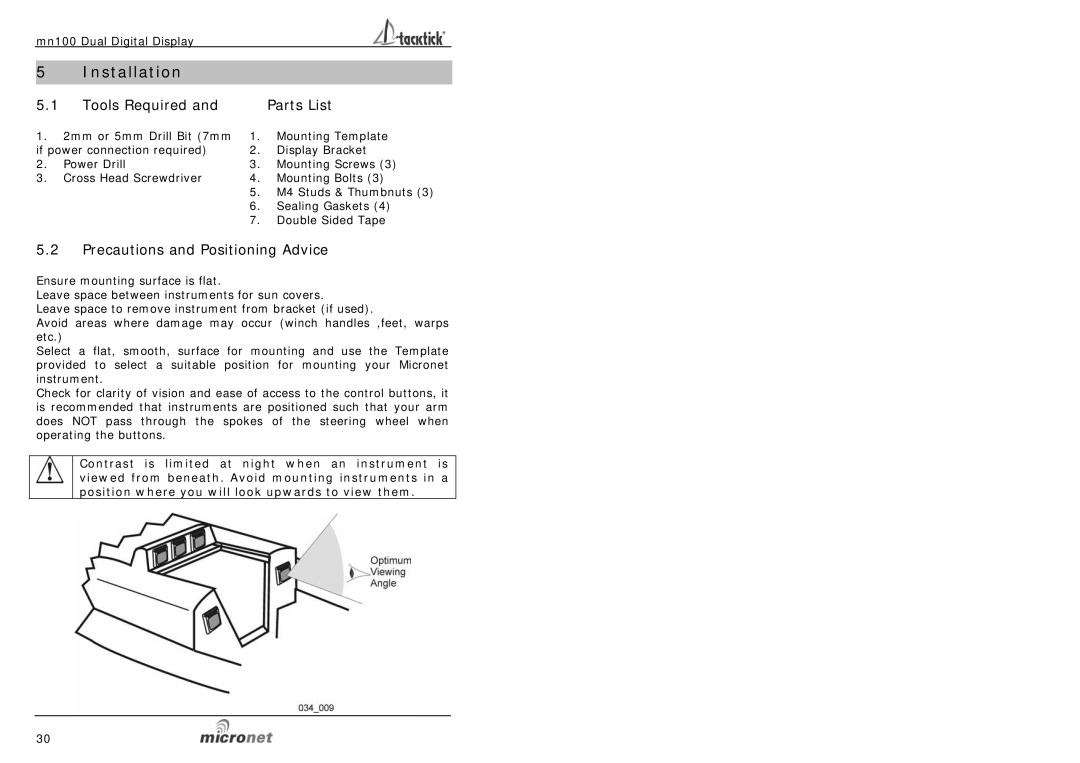
Check for clarity of vision and ease of access to the control buttons, it is recommended that instruments are positioned such that your arm does NOT pass through the spokes of the steering wheel when operating the buttons.
Contrast is limited at night when an instrument is viewed from beneath. Avoid mounting instruments in a position where you will look upwards to view them.
30