Processes
OM-4428215 932K
Description
File Engine Drive
From Miller to You
Table of Contents
Troubleshooting
Arc Welding Hazards
Symbol Usage
Electric Shock can kill
HOT Parts can cause severe burns
Buildup of GAS can injure or kill
Fumes and Gases can be hazardous
ARC Rays can burn eyes and skin
Welding can cause fire or explosion
Compressed Air Hazards
Engine Hazards
HOT Parts can cause burns and injury
Welding Wire can cause injury
Fire or Explosion hazard
Falling Unit can cause injury
California Proposition 65 Warnings
Principal Safety Standards
EMF Information
Radiation can cause interference
− Consignes DE Sécurité − Lire Avant Utilisation
Signification des symboles
UN Choc Électrique peut tuer
Indique des instructions spécifiques
LES Fumées ET LES GAZ peuvent être dangereux
DES Pièces Chaudes peuvent provoquer des brûlures graves
LE Soudage peut provoquer un in cendie ou une explosion
LE Bruit peut affecter l’ouïe
DES Organes Mobiles peuvent pro voquer des blessures
’EXPLOSION DE LA Batterie peu
’AIR Comprimé peut provoquer des blessures
LA Chaleur DU Moteur peut pro- voquer un incendie
Risque D’INCENDIE OU D’EXPLO- Sion
DES Organes Mobiles peuvent provoquer des blessures
LE Surchauffement peut endom- mager le moteur électrique
LES Fils DE Soudage peuvent provoquer des blessures
’EMPLOI Excessif peut
Principales normes de sécurité
Proposition californienne 65 Avertissements
Information EMF
En ce qui concerne les implants médicaux
− 50 h Std
− Definitions
Std
CC Models
Manufacturer’s Rating Labels
Some symbols are found only on CE products
Symbols And Definitions
Weld, Power, And Engine Specifications
− Specifications
Dimensions, Weights, And Operating Angles
Lifting Eye Weight Rating
Volts
Volt-Ampere Curves For CC Models
MIG Mode
Stick Mode
TIG Mode
Volt-Ampere Curves For CC/CV Models
Fuel Consumption
Curve shows typical fuel use under weld or power loads
Duty Cycle And Overheating
AC Generator Power Curve
100% Duty Cycle At 500 Amperes
12 kVA/kW Single-Phase AC Output No Weld Load
Optional Three-Phase Generator Curves
20 kVA/kW Three-Phase AC Output No Weld Load
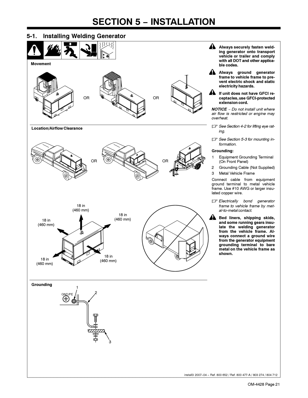
Installing Welding Generator
− Installation
Location/Airflow Clearance
Grounding1
Using Lifting Eye
Mounting Welding Generator
After installing cylinder, wait at
Installing Exhaust Pipe
Stop engine and let cool
Connecting The Battery
Activating The Dry Charge Battery If Applicable
Deutz F4L2011 Engine
Engine Prestart Checks
Deutz F3L912 Engine
Fuel
Correct Installation
Connecting To Weld Output Terminals
Stick and TIG Welding
MIG and Fcaw Welding
Selecting Weld Cable Sizes
Connecting to Weld
45 m 60 m 70 m 90 m 105 m 120 m
Output terminals
Socket
Connecting To Remote 14 Receptacle RC14 On CC/CV Models
Front Panel Controls For CC Models See Section
− Operating Welding Generator − CC Models
To Start
Engine Starting Controls
Engine Gauges And Meters
Weld Controls
Weld Control/Arc Condition Information Label
Remote Amperage Control On CC Models Optional
Example Combination Remote Amperage Control Stick
Work like a Pro
Front Panel Controls For CC/CV Models See Section
− Operating Welding Generator − CC/CV Models
14 AC/DC Voltmeter Optional
Voltage/Amperage Adjust Switch And Remote 14 Receptacle
Process/Contactor Switch Settings
Process/Contactor Switch On CC/CV Models
Example Combination Remote Amperage Control TIG
Remote Voltage/Amperage Control On CC/CV Models Optional
Volt And 240 Volt Receptacles
− Operating Auxiliary Equipment
At least once a month, run en
If a Supplementary
Close
Rear Of Panel
Connections
Are made Generator
240 V 15 a AC South African Receptacle RC1
Optional Generator Power Receptacles Standard Models
Supplementary Protector CB2 Supplementary Protector CB3
Generator power is not affected by weld output
Generator Power Receptacles Export Models
Maintenance Label Deutz F4L2011-Powered Units
− Maintenance Deutz F4L2011−POWERED Units
Routine Maintenance Deutz F4L2011-Powered Units
Checking Generator Brushes
To clean air filter
Servicing Air Cleaner Deutz F4L2011-Powered Units
Covering cleanout hole
Spark Arrestor Muffler Cleanout Plug
Blow out cleanout hole. If nothing
Reinstall cleanout plug Tools Needed 3/8
Standard Models
Adjusting Engine Speed Deutz F4L2011-Powered Units
Do not set engine speed higher than specified
Models With Automatic Idle Optional
To drain water from fuel system
To change oil and filter
To replace primary fuel filter
To replace secondary fuel filter
When a supplementary protector
Overload Protection Deutz F4L2011-Powered Units
Maintenance Label Deutz F3L912-Powered Units
− Maintenance Deutz F3L912−POWERED Units
Routine Maintenance Deutz F3L912-Powered Units
Checking Generator Brushes
Clean or replace primary element if dirty
Ment is not covered by the warranty
See note above before cleaning. Re
Cleanings
Spark Arrestor Muffler Cleanout Plug
Adjusting Engine Speed Deutz F3L912-Powered Units
To change oil and filter
Overload Protection Deutz F3L912-Powered Units
Troubleshooting
− Troubleshooting
Welding − CC Models
Welding − CC/CV Models
Optional Three-Phase Generator Power CC/CV Models Only
Standard Generator Power
Engine
− Electrical Diagrams
215 221-E
OM-4428
235 275-A
OM-4428
215 806-E
OM-4428
235 276-A
OM-4428
215 807-D
OM-4428
215 808-D
Wetstacking
− RUN-IN Procedure
Welding Generator
Keep exhaust and pipe away
Run-In Procedure Using Load Bank
From flammables
Specifications section in this
Run-In Procedure Using Resistance Grid
Just generator A/V control so
Manual
Selecting Equipment
− Generator Power Guidelines
Grounding Generator To Truck Or Trailer Frame
Electrically Bond Generator
How Much Power Does Equipment Require?
Grounding When Supplying Building Systems
Use ground device as stated in electrical codes
Amperes x Volts = Watts
Approximate Power Requirements For Farm/Home Equipment
Approximate Power Requirements For Industrial Motors
Industrial Motors Rating Starting Watts Running Watts
Farm/Home Equipment Rating Starting Watts Running Watts
Contractor Rating Starting Watts Running Watts
Approximate Power Requirements For Contractor Equipment
How Much Power Can Generator Supply?
Power Required To Start Motor
Single-Phase Induction Motor Starting Requirements
KVA/HP x HP x 1000 / Volts = Starting Amperage
Typical Connections To Supply Standby Power
Selecting Extension Cord Use Shortest Cord Possible
CC CC Models Only CV CC/CV Models Only
− Parts List
Deutz F4L2011 en
Dia Part Description Quantity
Dia Part Description Quantity Mkgs
CC191
Control Box Assembly − CC Models
PLG3
Control Box Assembly − CC/CV Models
193 SWITCH, rotary 6 position gold contacts
Panel, Front w/Components − CC Models
GFCI1
Temp
Panel, Front w/Components − CC/CV Models -1Item
Panel, Front w/Components − CC/CV Models
PC6 192
PC4, PC5 189
2827
Hardware is common
602 SCREW, .312−18x .75 hexwhd.66d stl pld slffmg tap−rw 601
Main Rectifier Assembly -1Item
Main Rectifier Assembly
Page
Your distributor also gives
Service
Support
Miller Electric Mfg. Co
To locate a Distributor or Service Agency visit
For assistance in filing or settling claims, contact
Your distributor and/or equipment manufacturer’s