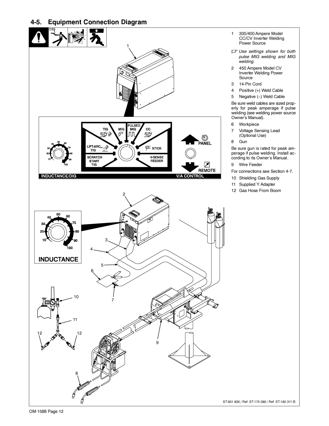
4-5. Equipment Connection Diagram
1
2
3
4
5 ![]()
6
1300/400 Ampere Model CC/CV Inverter Welding Power Source
.Use settings shown for both
pulse MIG welding and MIG welding.
2450 Ampere Model CV Inverter Welding Power Source
3
4Positive (+) Weld Cable
5Negative (−) Weld Cable
Be sure weld cables are sized prop- erly for peak amperage if pulse welding (see welding power source Owner’s Manual).
6Workpiece
7Voltage Sensing Lead (Optional Use)
8Gun
Be sure gun is rated for peak am- perage if pulse welding. Install ac- cording to its Owner’s Manual.
9 Wire Feeder
For connections see Section
10Shielding Gas Supply
11Supplied Y Adapter
12Gas Hose From Boom
10
11
7
1212
9
8
