7-2. Optional Dual Schedule Switch Diagrams
1 | 1 | ||
2 | 2 | 2 | 2 |
A | 3 | 1 | 2 |
|
| A | 3 |
B | 4 | B | 4 |
| 3 |
|
|
| 4 |
|
| 1 | Adapter | 1 | Trigger | 1 | |
TR | 2 | 2 |
| 2 | TR | 2 |
|
|
|
|
| ||
| 3 | 3 |
| 3 | 5 |
|
| B |
|
|
|
| |
A |
|
|
|
|
| 1 |
| 4 | 4 |
|
|
| 3 |
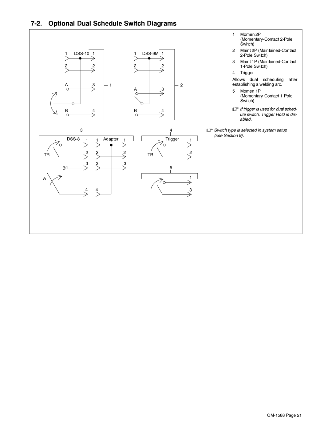
1Momen 2P
2Maint 2P
3Maint 1P
4Trigger
Allows dual scheduling after establishing a welding arc.
5Momen 1P
.If trigger is used for dual sched-
ule switch, Trigger Hold is dis- abled.
.Switch type is selected in system setup (see Section 9).