4-7. Control Box Connections
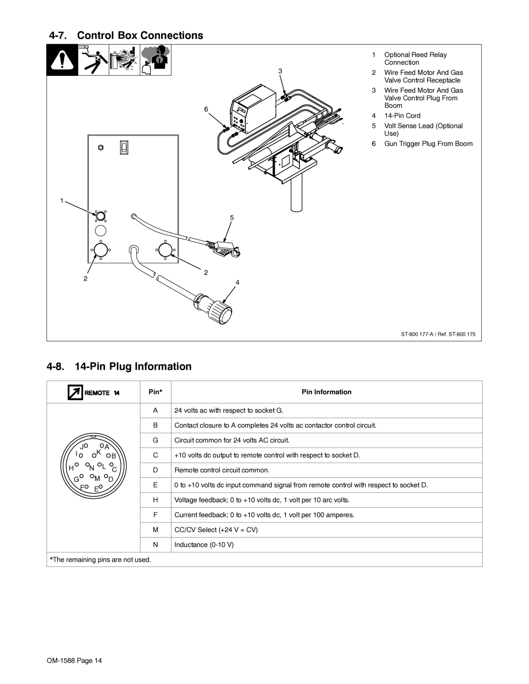
| 1 | Optional Reed Relay | |
|
| Connection | |
3 | 2 | Wire Feed Motor And Gas | |
|
| Valve Control Receptacle | |
| 3 | Wire Feed Motor And Gas | |
|
| Valve Control Plug From | |
6 |
| Boom | |
4 | |||
| |||
| 5 | Volt Sense Lead (Optional | |
|
| Use) | |
| 6 | Gun Trigger Plug From Boom |
1
5
2 | 2 | |
4 | ||
|
4-8. 14-Pin Plug Information
|
|
| Pin* | Pin Information |
|
|
| A | 24 volts ac with respect to socket G. |
|
|
| B | Contact closure to A completes 24 volts ac contactor control circuit. |
I J |
| A B | G | Circuit common for 24 volts AC circuit. |
K | C | +10 volts dc output to remote control with respect to socket D. | ||
H | N | L C | D | Remote control circuit common. |
G | M | D | E | 0 to +10 volts dc input command signal from remote control with respect to socket D. |
F | E |
| ||
|
|
| ||
|
|
| H | Voltage feedback; 0 to +10 volts dc, 1 volt per 10 arc volts. |
|
|
| F | Current feedback; 0 to +10 volts dc, 1 volt per 100 amperes. |
|
|
| M | CC/CV Select (+24 V = CV) |
|
|
| N | Inductance |
*The remaining pins are not used.