.A complete Parts List is available at www.MillerWelds.com
4-7. Installing Gas Supply
1
2
3
7 4
Argon Gas Or Mixed Gas
5 | 1 |
2
3
8 9
CO2 Gas
6 ![]()
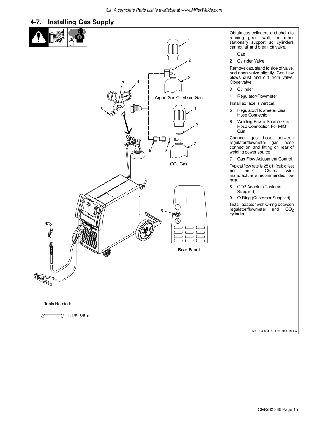
Obtain gas cylinders and chain to running gear, wall, or other stationary support so cylinders cannot fall and break off valve.
1Cap
2Cylinder Valve
Remove cap, stand to side of valve, and open valve slightly. Gas flow blows dust and dirt from valve. Close valve.
3Cylinder
4Regulator/Flowmeter
Install so face is vertical.
5Regulator/Flowmeter Gas Hose Connection
6Welding Power Source Gas Hose Connection For MIG Gun
Connect gas hose between regulator/flowmeter gas hose connection, and fitting on rear of welding power source.
7 Gas Flow Adjustment Control
Typical flow rate is 25 cfh (cubic feet
per hour). Check wire manufacturer’s recommended flow rate.
8CO2 Adapter (Customer Supplied)
9
Install adapter with
Rear Panel
Tools Needed:
1-1/8, 5/8 in
Ref. 804