.A complete Parts List is available at www.MillerWelds.com
SECTION 6 − MAINTENANCE &TROUBLESHOOTING
6-1. Routine Maintenance
! | Disconnect power | .Maintain more often |
| before maintaining. | during severe conditions. |
n = Check | Z = Change | ~ = Clean | l = Replace |
* To be done by Factory Authorized Service Agent |
| ||
Every
3 Months
| l Unreadable Labels | ~ Weld Terminals | nl Weld Cables |
Every |
|
|
|
6 | OR |
|
|
Months |
|
| |
|
|
| |
| ~ Inside Unit | n Apply Light Coat Of Oil |
|
|
| Or Grease To Drive Motor |
|
|
| Shaft |
|
Reference
6-2. Unit Overload
Thermostats TP1 in rectifier SR1 and TP2 in stabilizer Z1 protect the unit from damage due to overheating. If TP1 and/or TP2 opens welding output will shut off, and the Over Temp light will turn on. Wait until Over Temp light turns off before trying to weld.
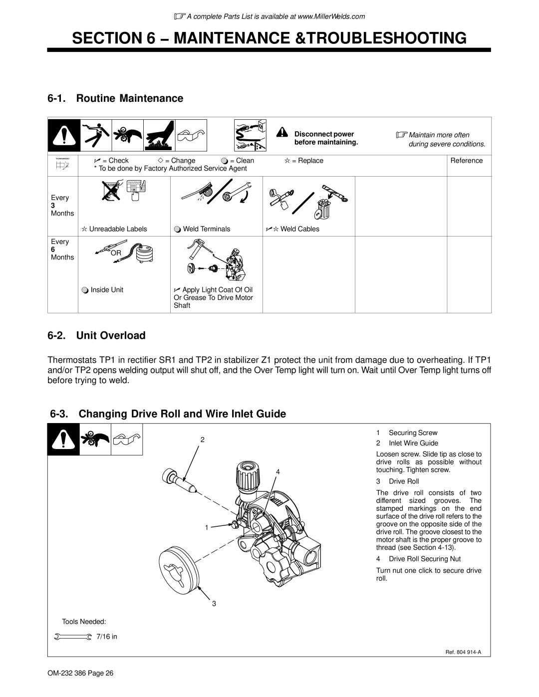
6-3. Changing Drive Roll and Wire Inlet Guide
2 |
|
| 1 | Securing Screw |
|
| 2 | Inlet Wire Guide | |
|
|
| ||
|
|
| Loosen screw. Slide tip as close to | |
|
|
| drive rolls as possible without | |
|
| 4 | touching. Tighten screw. | |
|
|
|
| |
|
|
| 3 | Drive Roll |
|
|
| The drive roll consists of two | |
|
|
| different sized grooves. The | |
|
|
| stamped markings on the end | |
|
|
| surface of the drive roll refers to the | |
| 1 |
| groove on the opposite side of the | |
|
| drive roll. The groove closest to the | ||
|
|
| ||
|
|
| motor shaft is the proper groove to | |
|
|
| thread (see Section | |
|
|
| 4 Drive Roll Securing Nut | |
|
|
| Turn nut one click to secure drive | |
|
|
| roll. |
|
|
| 3 |
|
|
Tools Needed: 7/16 in
Ref. 804