B. Connecting Single-Phase Input Power
1 ![]()
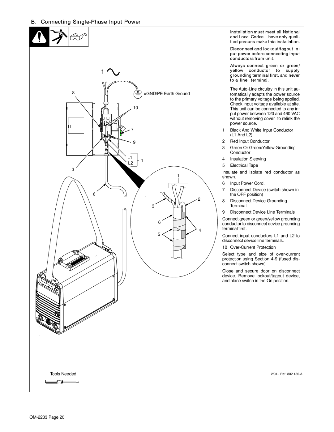
8 | =GND/PE Earth Ground |
10
YInstallation must meet all National and Local Codes − have only quali- fied persons make this installation.
YDisconnect and lockout/tagout in- put power before connecting input conductors from unit.
YAlways connect green or green/ yellow conductor to supply grounding terminal first, and never to a line terminal.
.The
7 |
|
| 1 | Black And White Input Conductor |
|
|
|
| (L1 And L2) |
9 |
|
| 2 | Red Input Conductor |
|
|
| 3 | Green Or Green/Yellow Grounding |
L1 |
|
|
| Conductor |
1 |
| 4 | Insulation Sleeving | |
L2 |
| |||
| 5 | Electrical Tape | ||
|
| |||
3 |
|
| ||
|
| Insulate and isolate red conductor as | ||
| 1 |
| ||
|
| shown. | ||
|
|
| 6 | Input Power Cord. |
6 |
|
| 7 | Disconnect Device (switch shown in |
| 2 |
| the OFF position) | |
|
| 8 | Disconnect Device Grounding | |
|
|
| ||
| 3 |
|
| Terminal |
|
|
| 9 | Disconnect Device Line Terminals |
6 |
|
| Connect green or green/yellow grounding |
|
| conductor to disconnect device grounding | |
|
| 4 | terminal first. |
5 |
| Connect input conductors L1 and L2 to | |
|
| ||
|
|
| disconnect device line terminals. |
|
|
| 10 |
|
|
| Select type and size of |
|
|
| protection using Section |
|
|
| connect switch shown). |
|
|
| Close and secure door on disconnect |
|
|
| device. Remove lockout/tagout device, |
|
|
| and place switch in the On position. |
Tools Needed: | 2/04 - Ref. 802 |
|