5.Operating the Welding Generator
5.1Front Panel Controls
Ref.
YHeavy loading during first 50 hours will damage engine. Keep load less than 225A (weld) or 7 kVA (power) for first 50 hours.
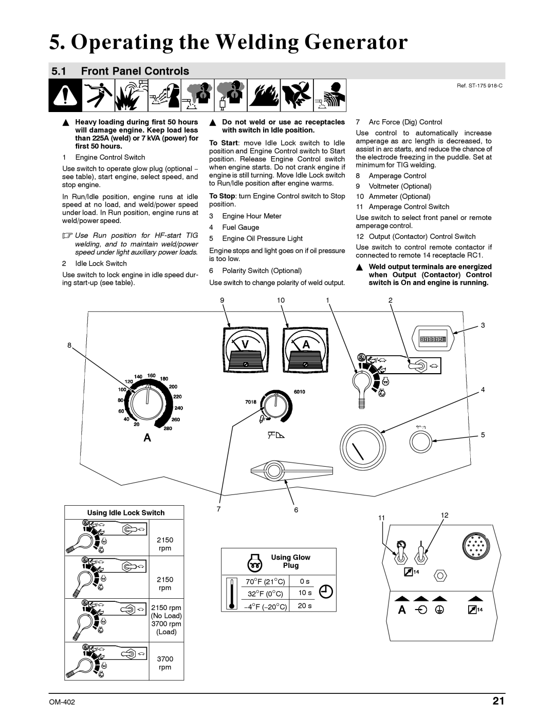
1 Engine Control Switch
Use switch to operate glow plug (optional − see table), start engine, select speed, and stop engine.
In Run/Idle position, engine runs at idle speed at no load, and weld/power speed under load. In Run position, engine runs at weld/power speed.
.Use Run position for
2 Idle Lock Switch
Use switch to lock engine in idle speed dur- ing
8
Using Idle Lock Switch
2150 rpm
2150 rpm
2150 rpm (No Load) 3700 rpm (Load)
3700 rpm
YDo not weld or use ac receptacles with switch in Idle position.
To Start: move Idle Lock switch to Idle position and Engine Control switch to Start position. Release Engine Control switch when engine starts. Do not crank engine if engine is still turning. Move Idle Lock switch to Run/Idle position after engine warms.
To Stop: turn Engine Control switch to Stop position.
3Engine Hour Meter
4Fuel Gauge
5Engine Oil Pressure Light
Engine stops and light goes on if oil pressure is too low.
6 Polarity Switch (Optional)
Use switch to change polarity of weld output.
9 | 10 | 1 |
76
| Using Glow | |
| Plug | |
70°F (21°C) | 0 s | |
° | ° | 10 s |
32 F (0 C) |
| |
° | ° | 20 s |
−4 F (−20 C) |
| |
7 Arc Force (Dig) Control
Use control to automatically increase amperage as arc length is decreased, to assist in arc starts, and reduce the chance of the electrode freezing in the puddle. Set at minimum for TIG welding.
8Amperage Control
9Voltmeter (Optional)
10Ammeter (Optional)
11Amperage Control Switch
Use switch to select front panel or remote amperage control.
12 Output (Contactor) Control Switch
Use switch to control remote contactor if connected to remote 14 receptacle RC1.
YWeld output terminals are energized when Output (Contactor) Control switch is On and engine is running.
2
3
4
5
1112
21 |