6.Operating Auxiliary Equipment
6.1Auxiliary Power Receptacles
.Place Engine Control switch in Run
position to maintain weld/power speed under light auxiliary power loads.
.Press button to reset circuit breaker. If a
circuit breaker continues to open, contact a Factory Authorized Service Agent.
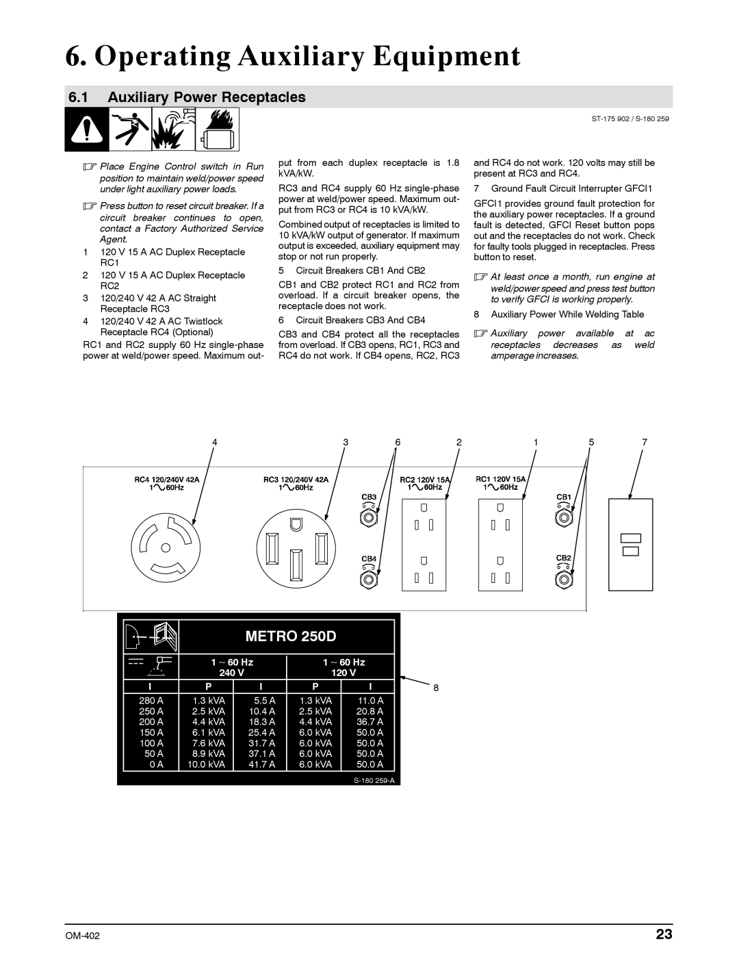
1120 V 15 A AC Duplex Receptacle RC1
2120 V 15 A AC Duplex Receptacle RC2
3120/240 V 42 A AC Straight Receptacle RC3
4120/240 V 42 A AC Twistlock Receptacle RC4 (Optional)
RC1 and RC2 supply 60 Hz
put from each duplex receptacle is 1.8 kVA/kW.
RC3 and RC4 supply 60 Hz
Combined output of receptacles is limited to 10 kVA/kW output of generator. If maximum output is exceeded, auxiliary equipment may stop or not run properly.
5 Circuit Breakers CB1 And CB2
CB1 and CB2 protect RC1 and RC2 from overload. If a circuit breaker opens, the receptacle does not work.
6 Circuit Breakers CB3 And CB4
CB3 and CB4 protect all the receptacles from overload. If CB3 opens, RC1, RC3 and RC4 do not work. If CB4 opens, RC2, RC3
and RC4 do not work. 120 volts may still be present at RC3 and RC4.
7 Ground Fault Circuit Interrupter GFCI1
GFCI1 provides ground fault protection for the auxiliary power receptacles. If a ground fault is detected, GFCI Reset button pops out and the receptacles do not work. Check for faulty tools plugged in receptacles. Press button to reset.
.At least once a month, run engine at
weld/power speed and press test button to verify GFCI is working properly.
8 Auxiliary Power While Welding Table
.Auxiliary power available at ac receptacles decreases as weld amperage increases.
4 |
|
|
|
| 3 | 6 | 2 | 1 | 5 | 7 | |||||
|
|
|
|
|
|
|
|
|
|
|
|
|
|
|
|
|
|
|
|
|
|
|
|
|
|
|
|
|
|
|
|
|
|
|
|
|
|
|
|
|
|
|
|
|
|
|
|
|
|
|
|
|
|
|
|
|
|
|
|
|
|
|
|
|
|
|
|
|
|
|
|
|
|
|
|
|
|
|
|
|
|
|
|
|
|
|
|
|
|
|
|
|
|
|
|
|
|
|
|
|
|
|
|
|
|
|
|
|
|
|
|
|
|
|
|
|
|
|
|
|
|
|
|
|
|
|
|
|
| METRO 250D |
| |
| 1 ∼ 60 Hz | 1 ∼ 60 Hz | ||
| 240 V |
| 120 V |
|
I | P | I | P | I |
280 A | 1.3 kVA | 5.5 A | 1.3 kVA | 11.0 A |
250 A | 2.5 kVA | 10.4 A | 2.5 kVA | 20.8 A |
200 A | 4.4 kVA | 18.3 A | 4.4 kVA | 36.7 A |
150 A | 6.1 kVA | 25.4 A | 6.0 kVA | 50.0 A |
100 A | 7.6 kVA | 31.7 A | 6.0 kVA | 50.0 A |
50 A | 8.9 kVA | 37.1 A | 6.0 kVA | 50.0 A |
0 A | 10.0 kVA | 41.7 A | 6.0 kVA | 50.0 A |
8
23 |