SECTION 11 − GENERATOR POWER GUIDELINES
NOTE
The views in this section are intended to be representative of all
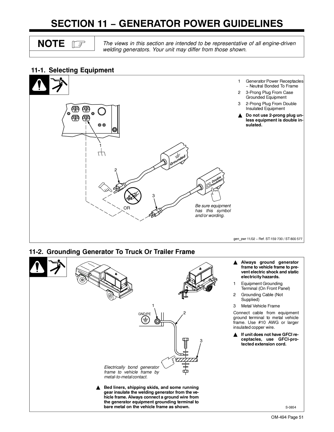
11-1. Selecting Equipment
1 Generator Power Receptacles
− Neutral Bonded To Frame
2
Grounded Equipment
3
Insulated Equipment
Y Do not use
1
2
| 3 | |
OR | Be sure equipment | |
has this symbol | ||
| ||
| and/or wording. |
gen_pwr 11/02 − Ref.
11-2. Grounding Generator To Truck Or Trailer Frame
1
GND/PE2
3
Electrically bond generator ![]() frame to vehicle frame by
frame to vehicle frame by
YBed liners, shipping skids, and some running gear insulate the welding generator from the ve- hicle frame. Always connect a ground wire from the generator equipment grounding terminal to bare metal on the vehicle frame as shown.
YAlways ground generator frame to vehicle frame to pre- vent electric shock and static electricity hazards.
1Equipment Grounding Terminal (On Front Panel)
2Grounding Cable (Not Supplied)
3Metal Vehicle Frame
Connect cable from equipment ground terminal to metal vehicle frame. Use #10 AWG or larger insulated copper wire.
YIf unit does not have GFCI re- ceptacles, use