| Item |
| Dia. |
| Part | Description | Quantity |
| No. |
| Mkgs. |
| No. | ||
|
|
|
|
|
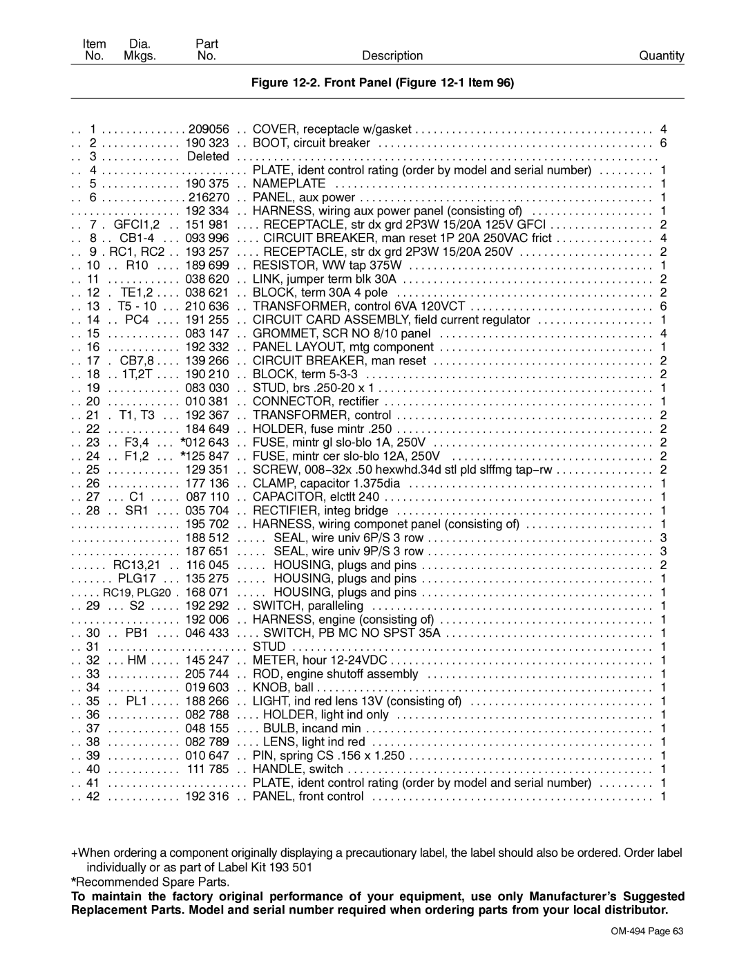
| Figure |
|
|
|
|
|
|
|
|
|
. . | 1 . | . . | . . . . . . | . . . . | . 209056 | . . COVER, receptacle w/gasket | . . . 4 |
. . | 2 . | . . | . . . . . . | . . . . | 190 323 | . . BOOT, circuit breaker | . . . 6 |
. . | 3 . | . . | . . . . . . | . . . . | Deleted | . . . . . . . . . . . . . . . . . . . . . . . . . . . . . . . . . . . . . . . . . . . . . . . . . . . . . . . . . . . . . . . . . | . . . . |
. . | 4 . | . . | . . . . . . | . . . . | . . . . . . . . . | . . PLATE, ident control rating (order by model and serial number) | . . . 1 |
. . | 5 . | . . | . . . . . . | . . . . | 190 375 | . . NAMEPLATE | . . . 1 |
. . | 6 . | . . | . . . . . . | . . . . | . 216270 | . . PANEL, aux power | . . . 1 |
. . | . . . . | . . | . . . . . . | . . . . | 192 334 | . . HARNESS, wiring aux power panel (consisting of) | . . . 1 |
. . | 7 . GFCI1,2 . . 151 981 | . . . . RECEPTACLE, str dx grd 2P3W 15/20A 125V GFCI | . . . 2 | ||||
. . | 8 . | . | . . . 093 996 | . . . . CIRCUIT BREAKER, man reset 1P 20A 250VAC frict | . . . 4 | ||
. . | 9 . RC1, RC2 . . | 193 257 | . . . . RECEPTACLE, str dx grd 2P3W 15/20A 250V | . . . 2 | |||
. . 10 | . . | R10 | . . . . 189 699 | . . RESISTOR, WW tap 375W | . . . 1 | ||
. . 11 | . . | . . . . . . | . . . . | 038 620 | . . LINK, jumper term blk 30A | . . . 2 | |
. . 12 | . TE1,2 | . . . . | 038 621 | . . BLOCK, term 30A 4 pole | . . . 2 | ||
. . 13 | . T5 - 10 . . . 210 636 | . . TRANSFORMER, control 6VA 120VCT | . . . 6 | ||||
. . 14 | . . PC4 | . . . . 191 255 | . . CIRCUIT CARD ASSEMBLY, field current regulator | . . . 1 | |||
. . 15 | . . | . . . . . . | . . . . | 083 147 | . . GROMMET, SCR NO 8/10 panel | . . . 4 | |
. . 16 | . . | . . . . . . | . . . . | 192 332 | . . PANEL LAYOUT, mtg component | . . . 1 | |
. . 17 | . CB7,8 | . . . . | 139 266 | . . CIRCUIT BREAKER, man reset | . . . 2 | ||
. . 18 | . . 1T,2T | . . . . | 190 210 | . . BLOCK, term | . . . 2 | ||
. . 19 | . . | . . . . . . | . . . . | 083 030 | . . STUD, | . . . 1 | |
. . 20 | . . | . . . . . . | . . . . | 010 381 | . . CONNECTOR, rectifier | . . . 1 | |
. . 21 | . T1, T3 | . . . 192 367 | . . TRANSFORMER, control | . . . 2 | |||
. . 22 | . . | . . . . . . | . . . . | 184 649 | . . HOLDER, fuse mintr .250 | . . . 2 | |
. . 23 | . . | F3,4 | . . . | *012 643 | . . FUSE, mintr gl | . . . 2 | |
. . 24 | . . | F1,2 | . . . | *125 847 | . . FUSE, mintr cer | . . . 2 | |
. . 25 | . . | . . . . . . | . . . . | 129 351 | . . SCREW, 008−32x .50 hexwhd.34d stl pld slffmg tap−rw | . . . 2 | |
. . 26 | . . | . . . . . . | . . . . | 177 136 | . . CLAMP, capacitor 1.375dia | . . . 1 | |
. . 27 | . . . C1 | 087 110 | . . CAPACITOR, elctlt 240 | . . . 1 | |||
. . 28 | . . SR1 | . . . . 035 704 | . . RECTIFIER, integ bridge | . . . 1 | |||
. . | . . . . | . . | . . . . . . | . . . . | 195 702 | . . HARNESS, wiring componet panel (consisting of) | . . . 1 |
. . | . . . . | . . . . . . . . | . . . . | 188 512 | . . . . . SEAL, wire univ 6P/S 3 row | . . . 3 | |
. . | . . . . | . . . . . . . . | . . . . | 187 651 | . . . . . SEAL, wire univ 9P/S 3 row | . . . 3 | |
. . | . . . . | RC13,21 . . | 116 045 | . . . . . HOUSING, plugs and pins | . . . 2 | ||
. . | . . . . | . | PLG17 | . . . 135 275 | . . . . . HOUSING, plugs and pins | . . . 1 | |
. . . . . RC19, PLG20 . 168 071 | . . . . . HOUSING, plugs and pins | . . . 1 | |||||
. . 29 | . . . S2 | 192 292 | . . SWITCH, paralleling | . . . 1 | |||
. . | . . . . | . . . . . . . . | . . . . | 192 006 | . . HARNESS, engine (consisting of) | . . . 1 | |
. . 30 | . . PB1 | . . . . 046 433 | . . . . SWITCH, PB MC NO SPST 35A | . . . 1 | |||
. . 31 | . . | . . . . . . | . . . . | . . . . . . . . . | . . STUD | . . . 1 | |
. . 32 | . . . HM . | . . . . | 145 247 | . . METER, hour | . . . 1 | ||
. . 33 | . . | . . . . . . | . . . . | 205 744 | . . ROD, engine shutoff assembly | . . . 1 | |
. . 34 | . . | . . . . . . | . . . . | 019 603 | . . KNOB, ball | . . . 1 | |
. . 35 | . . | PL1 . | . . . . | 188 266 | . . LIGHT, ind red lens 13V (consisting of) | . . . 1 | |
. . 36 | . . | . . . . . . | . . . . | 082 788 | . . . . HOLDER, light ind only | . . . 1 | |
. . 37 | . . | . . . . . . | . . . . | 048 155 | . . . . BULB, incand min | . . . 1 | |
. . 38 | . . | . . . . . . | . . . . | 082 789 | . . . . LENS, light ind red | . . . 1 | |
. . 39 | . . | . . . . . . | . . . . | 010 647 | . . PIN, spring CS .156 x 1.250 | . . . 1 | |
. . 40 | . . | . . . . . . | . . . . | 111 785 | . . HANDLE, switch | . . . 1 | |
. . 41 | . . | . . . . . . | . . . . | . . . . . . . . . | . . PLATE, ident control rating (order by model and serial number) | . . . 1 | |
. . 42 | . . | . . . . . . | . . . . | 192 316 | . . PANEL, front control | . . . 1 | |
+When ordering a component originally displaying a precautionary label, the label should also be ordered. Order label individually or as part of Label Kit 193 501
*Recommended Spare Parts.
To maintain the factory original performance of your equipment, use only Manufacturer’s Suggested Replacement Parts. Model and serial number required when ordering parts from your local distributor.