Preparating your projector (Continue)
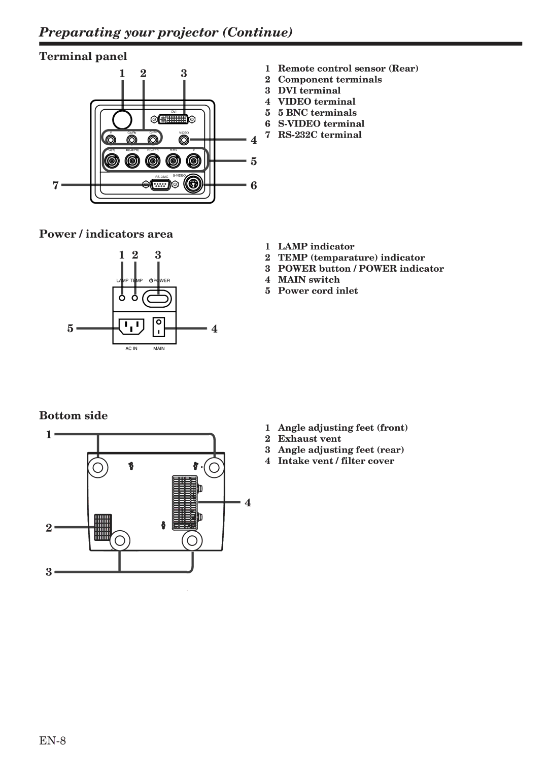
Terminal panel
1 |
| 2 |
| 3 |
|
|
| DVI |
|
Y | Cb/Pb | Cr/Pr |
| VIDEO |
G(Y) | B(Cb/Pb) | R(Cr/Pr) | H/HV | V |
1Remote control sensor (Rear)
2Component terminals
3DVI terminal
4VIDEO terminal
55 BNC terminals
6
47
5
|
|
| ||
7 |
| 6 |
| |
|
|
| ||
Power / indicators area |
|
| ||
1 2 | 3 |
| 1 | LAMP indicator |
| 2 | TEMP (temparature) indicator | ||
|
|
| 3 | POWER button / POWER indicator |
LAMP TEMP | POWER |
| 4 | MAIN switch |
|
|
| 5 | Power cord inlet |
5 |
|
| 4 |
|
AC IN | MAIN |
Bottom side
1
1Angle adjusting feet (front)
2Exhaust vent
3Angle adjusting feet (rear)
4Intake vent / filter cover
4
2
3
