Preparing your projector (continued)
Overview
1
3 2 | 3 | 4 |
5 | 6 | 7 | 8 | 8 |
Control area
1 | 2 | 3 | 4 | 5 | 6 |
7 | 8 | 9 | 10 | 11 |
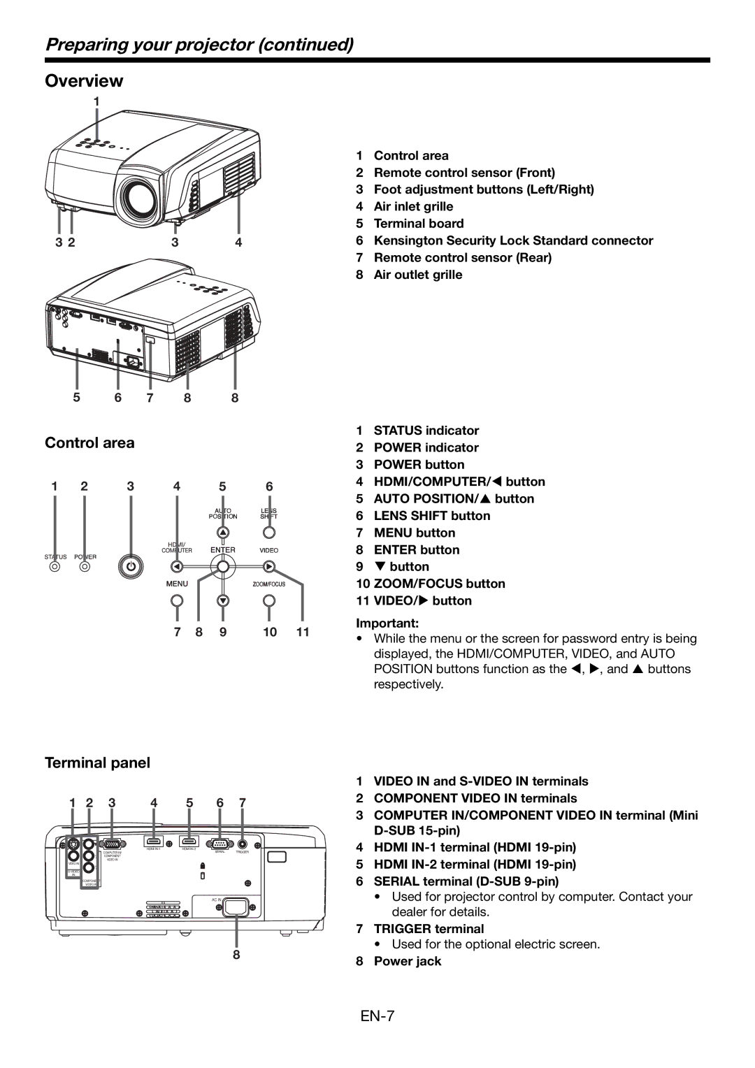
1 Control area
2 Remote control sensor (Front)
3Foot adjustment buttons (Left/Right)
4 Air inlet grille
5 Terminal board
6 Kensington Security Lock Standard connector
7 Remote control sensor (Rear)
8 Air outlet grille
1STATUS indicator
2 POWER indicator
3 POWER button
4 HDMI/COMPUTER/W button
5 AUTO POSITION/S button
6 LENS SHIFT button
7 MENU button
8 ENTER button
9 T button
10 ZOOM/FOCUS button
11 VIDEO/X button
Important:
•While the menu or the screen for password entry is being
displayed, the HDMI/COMPUTER, VIDEO, and AUTO POSITION buttons function as the W, X, and S buttons respectively.
Terminal panel
1 | 2 | 3 | 4 | 5 | 6 | 7 |
| HDMI | HDMI |
|
PB/ | COMPUTER IN/ | SERIAL | TRIGGER |
COMPONENT |
|
| |
CB |
|
| |
| VIDEO IN |
|
|
VIDEO IN |
|
|
|
PR/ |
|
|
|
CR |
|
|
|
|
|
| |
IN |
|
|
|
COMPONENT |
|
|
|
VIDEO IN |
|
|
|
AC IN
8
1VIDEO IN and
2 COMPONENT VIDEO IN terminals
3 COMPUTER IN/COMPONENT VIDEO IN terminal (Mini
4 HDMI
5 HDMI
6 SERIAL terminal
•Used for projector control by computer. Contact your dealer for details.
7TRIGGER terminal
• Used for the optional electric screen.
8 Power jack