VENT INSTALLATION
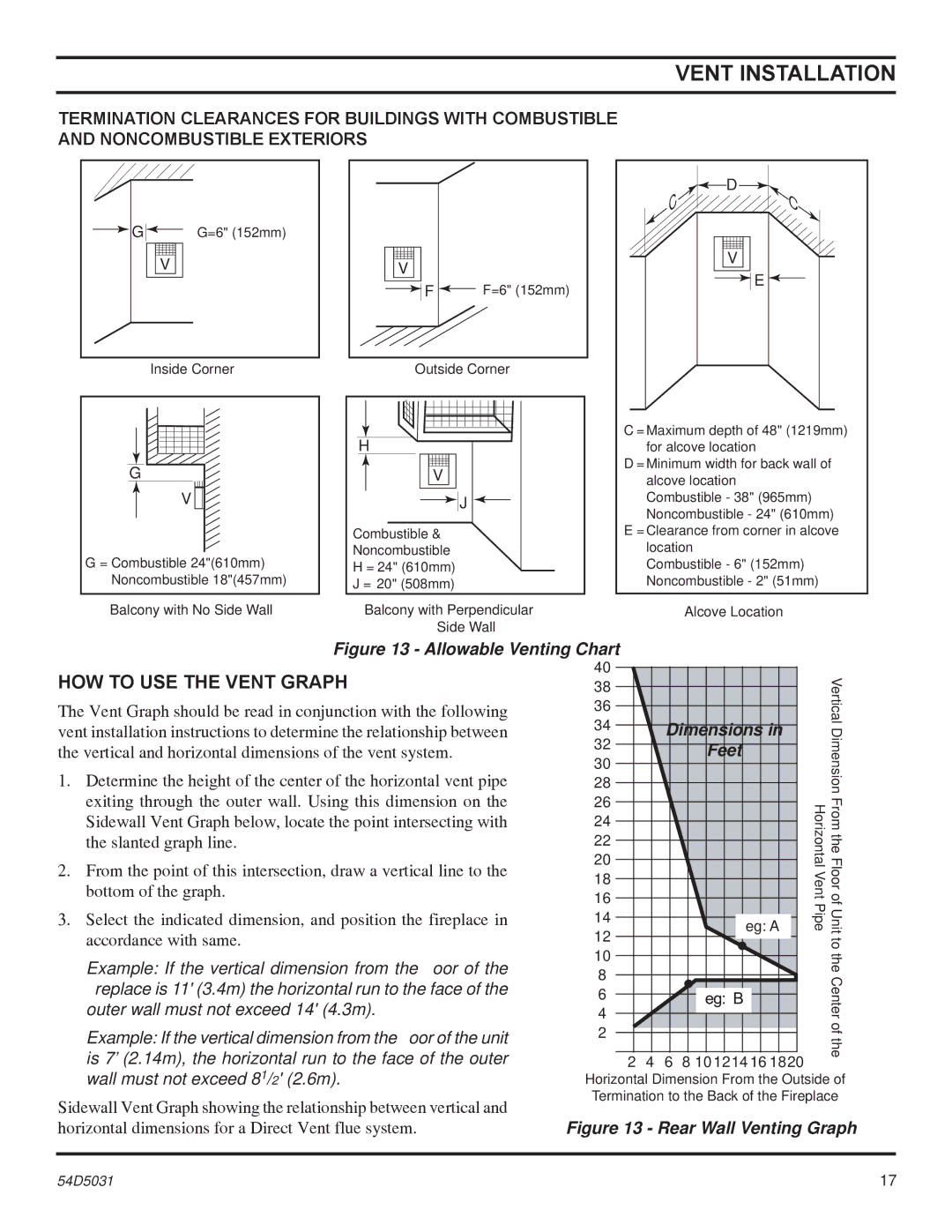
TERMINATION CLEARANCES FOR BUILDINGS WITH COMBUSTIBLE
AND NONCOMBUSTIBLE EXTERIORS
G |
|
| G=6" (152mm) |
|
V ![]()
![]()
Inside Corner
G
V ![]()
![]()
G = Combustible 24"(610mm) Noncombustible 18"(457mm)
V ![]()
![]()
![]()
![]() F
F ![]() F=6" (152mm)
F=6" (152mm)
Outside Corner
H |
V |
J |
Combustible & |
Noncombustible |
H = 24" (610mm) |
J = 20" (508mm) |
| D |
C | C |
|
V ![]()
![]()
![]() E
E ![]()
C = Maximum depth of 48" (1219mm) for alcove location
D = Minimum width for back wall of alcove location Combustible - 38" (965mm) Noncombustible - 24" (610mm)
E = Clearance from corner in alcove location
Combustible - 6" (152mm) Noncombustible - 2" (51mm)
Balcony with No Side Wall | Balcony with Perpendicular | Alcove Location |
| Side Wall |
|
Figure 13 - Allowable Venting Chart
HOW TO USE THE VENT GRAPH
The Vent Graph should be read in conjunction with the following vent installation instructions to determine the relationship between the vertical and horizontal dimensions of the vent system.
1.Determine the height of the center of the horizontal vent pipe exiting through the outer wall. Using this dimension on the Sidewall Vent Graph below, locate the point intersecting with the slanted graph line.
2.From the point of this intersection, draw a vertical line to the bottom of the graph.
3.Select the indicated dimension, and position the fireplace in accordance with same.
Example: If the vertical dimension from the floor of the fireplace is 11' (3.4m) the horizontal run to the face of the outer wall must not exceed 14' (4.3m).
Example: If the vertical dimension from the floor of the unit is 7’ (2.14m), the horizontal run to the face of the outer wall must not exceed 81/2' (2.6m).
Sidewall Vent Graph showing the relationship between vertical and horizontal dimensions for a Direct Vent flue system.
40 |
|
|
|
| Vertical |
38 |
|
|
|
| |
36 |
|
|
|
| |
34 |
| Dimensions in |
| ||
|
| Dimension | |||
32 |
|
| Feet |
| |
30 |
|
|
| ||
|
|
|
| ||
28 |
|
|
|
| |
26 |
|
|
|
| |
|
|
| Horizontal Vent Pipe | From the Floor of Unit | |
24 |
|
|
| ||
22 |
|
|
| ||
20 |
|
|
| ||
18 |
|
|
| ||
16 |
|
|
| ||
14 |
|
| eg: A | ||
12 |
|
| |||
|
|
|
| to | |
10 |
|
|
|
| |
|
|
|
| the | |
8 |
|
|
|
| |
|
|
|
| Center | |
6 |
|
|
|
| |
4 |
|
|
|
| |
2 |
|
|
|
| of |
|
|
|
| the | |
2 | 4 | 6 | 8 10 12 14 16 18 20 |
| |
|
| ||||
Horizontal Dimension From the Outside of Termination to the Back of the Fireplace
Figure 13 - Rear Wall Venting Graph
54D5031 | 17 |