Introduction
Antenna Installation and Removal
Before installing the antenna, ensure that the match between your radio and antenna is correct. Your radio’s model number is on a label attached to the back of your radio. A typical model number might be H09UCC9PW5AN. The fourth position of the model number (in this example “U”) identifies the
Radio Operating-Frequency Table
Fourth- Operating Fourth- Operating Fourth- Operating Fourth Operating Position Frequency Position Frequency Position Frequency Position Frequency
K | 136- | R | 403- | S | 450- | U | 806- |
| 178MHz |
| 470MHz |
| 512MHz |
| 870MHz |
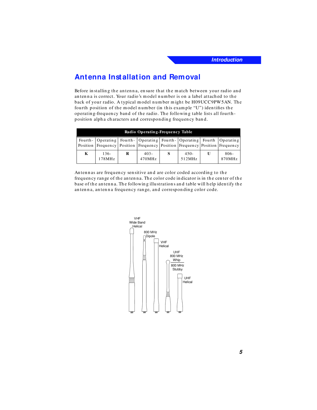
Antennas are frequency sensitive and are color coded according to the frequency range of the antenna. The color code indicator is in the center of the base of the antenna. The following illustrations and table will help identify the antenna, antenna frequency range, and corresponding color code.
| DESCRIPTION |
|
|
| ASTRO Antenna Id | ||
| ILLUSTRATOR | DATE | E N |
| EH | 12/8/92 |
|
VHF | EDITOR | DATE | C |
PR | 12/9/92 |
| |
Wide Band |
| LETTERIN | |
Helical |
| REQUIRES | |
|
|
| |
800 MHz |
|
|
|
Dipole |
|
|
|
| VHF |
|
|
| Helical |
|
|
| UHF |
|
|
| 800 MHz |
|
|
| Whip |
|
|
| 800 MHz |
|
|
| Stubby |
|
|
| UHF |
|
|
| Helical |
|
|
5