Manual
Wall Mounting (Optional)
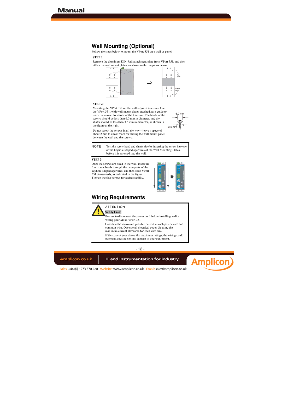
Follow the steps below to mount the VPort 351 on a wall or panel.
STEP 1:
Remove the aluminum
⇒
STEP 2:
Top plate
Bottom plate
Mounting the VPort 351 on the wall requires 4 screws. Use the VPort 351, with wall mount plates attached, as a guide to mark the correct locations of the 4 screws. The heads of the screws should be less than 6.0 mm in diameter, and the shafts should be less than 3.5 mm in diameter, as shown in the figure at the right.
Do not screw the screws in all the
6.0 mm
3.5 mm
NOTE Test the screw head and shank size by inserting the screw into one of the keyhole shaped apertures of the Wall Mounting Plates, before it is screwed into the wall.
STEP 3:
Once the screws are fixed in the wall, insert the four screw heads through the large parts of the
Tighten the four screws for added stability.
Wiring Requirements
ATTENTION
Safety First!
Be sure to disconnect the power cord before installing and/or wiring your Moxa VPort 351.
Calculate the maximum possible current in each power wire and common wire. Observe all electrical codes dictating the maximum current allowable for each wire size.
If the current goes above the maximum ratings, the wiring could overheat, causing serious damage to your equipment.
- 12 -
Amplicon.co.uk | IT and Instrumentation for industry |
Sales: +44 (0) 1273 570 220 Website: www.amplicon.co.uk Email: sales@amplicon.co.uk