Manual
Wiring the Redundant Power Inputs
The VPort 351 has two power inputs, labeled PWR1 and PWR2, on the
ATTENTION
The power for this product is intended to be supplied by a Listed Power Unit, with output marked LPS, and rated to deliver 12 to 32 VDC at a maximum of 740mA, or 18 to 30 VAC at a maximum of 890mA.
Wiring the Relay Output
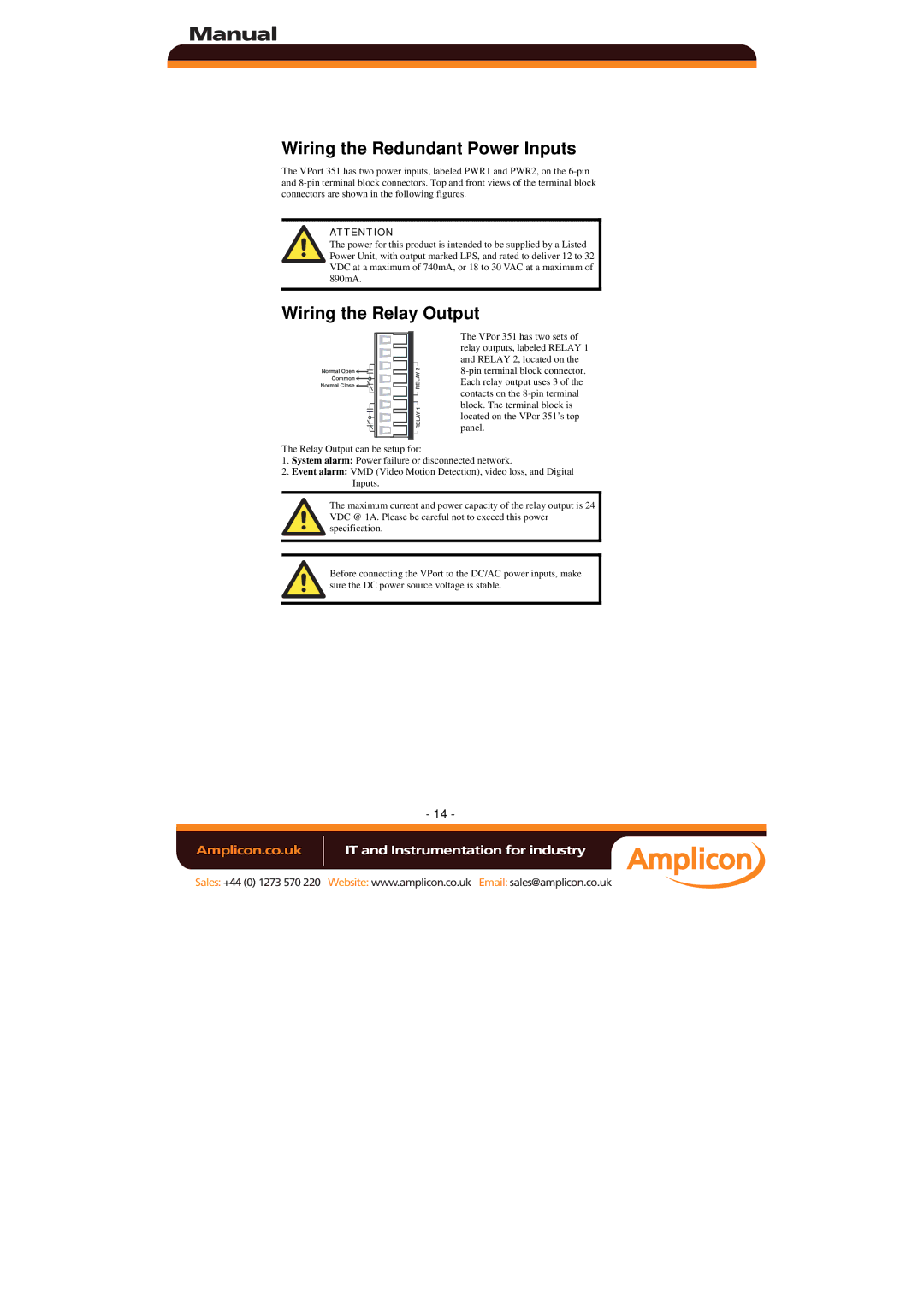
Normal Open ![]()
![]()
Common ![]()
![]()
Normal Close ![]()
![]()
![]()
![]()
![]()
![]()
![]() RELAY 1 RELAY 2
RELAY 1 RELAY 2
The VPor 351 has two sets of relay outputs, labeled RELAY 1 and RELAY 2, located on the
The Relay Output can be setup for:
1.System alarm: Power failure or disconnected network.
2.Event alarm: VMD (Video Motion Detection), video loss, and Digital Inputs.
The maximum current and power capacity of the relay output is 24 VDC @ 1A. Please be careful not to exceed this power specification.
Before connecting the VPort to the DC/AC power inputs, make sure the DC power source voltage is stable.
- 14 -
Amplicon.co.uk | IT and Instrumentation for industry |
Sales: +44 (0) 1273 570 220 Website: www.amplicon.co.uk Email: sales@amplicon.co.uk