Manual
Wiring the Digital Inputs
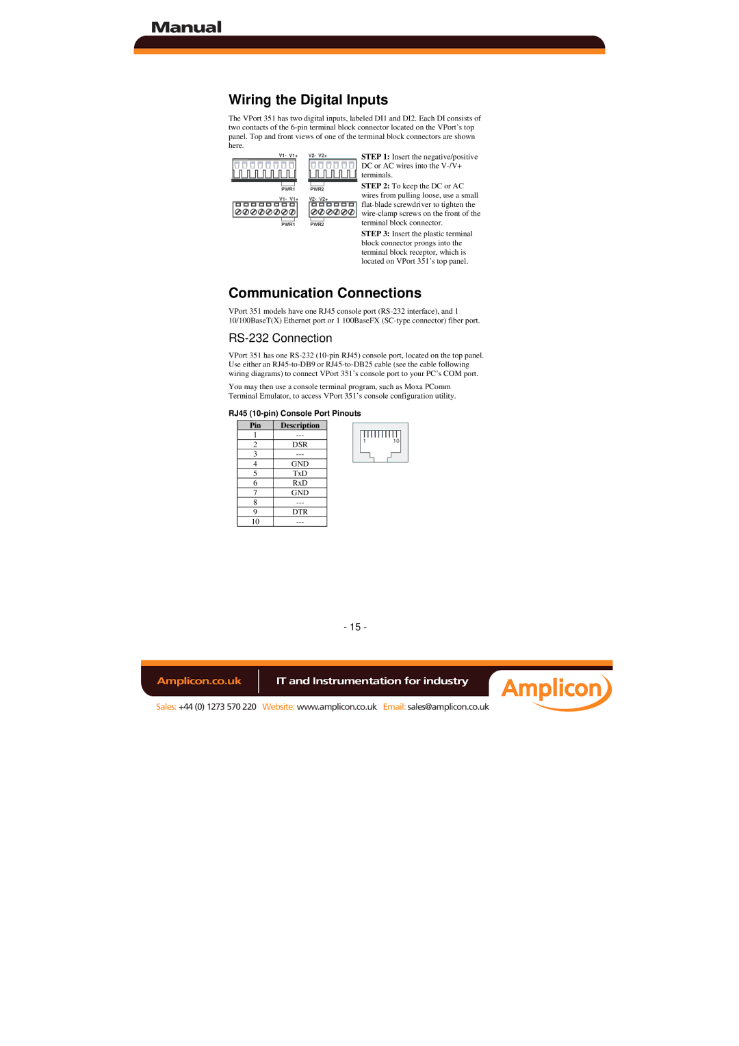
The VPort 351 has two digital inputs, labeled DI1 and DI2. Each DI consists of two contacts of the
V1- V1+ | V2- V2+ |
PWR1 | PWR2 |
V1- V1+ | V2- V2+ |
PWR1 | PWR2 |
STEP 1: Insert the negative/positive DC or AC wires into the
STEP 2: To keep the DC or AC wires from pulling loose, use a small
STEP 3: Insert the plastic terminal block connector prongs into the terminal block receptor, which is located on VPort 351’s top panel.
Communication Connections
VPort 351 models have one RJ45 console port
RS-232 Connection
VPort 351 has one
You may then use a console terminal program, such as Moxa PComm Terminal Emulator, to access VPort 351’s console configuration utility.
RJ45
Pin | Description |
|
|
|
|
| |
1 |
|
|
|
|
| ||
|
|
|
| 1 | 10 |
| |
2 | DSR | ||||||
|
|
|
|
| |||
3 |
|
|
|
|
| ||
4 | GND |
|
|
|
|
| |
|
|
|
|
| |||
5 | TxD |
|
|
|
|
| |
6 | RxD |
|
|
|
|
| |
7 | GND |
|
|
|
|
| |
8 |
|
|
|
|
| ||
9 | DTR |
|
|
|
|
| |
10 |
|
|
|
|
|
- 15 -
Amplicon.co.uk | IT and Instrumentation for industry |
Sales: +44 (0) 1273 570 220 Website: www.amplicon.co.uk Email: sales@amplicon.co.uk
