Manual
LED Indicators
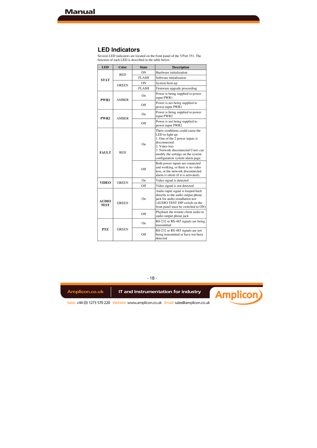
Several LED indicators are located on the front panel of the VPort 351. The function of each LED is described in the table below.
LED | Color | State | |
| RED | ON | |
STAT | FLASH | ||
| |||
GREEN | ON | ||
| |||
| FLASH | ||
|
| ||
PWR1 | AMBER | On | |
| |||
Off | |||
|
| ||
|
|
| |
PWR2 | AMBER | On | |
| |||
Off | |||
|
| ||
|
|
| |
|
| On | |
FAULT | RED |
| |
|
|
| |
|
| Off | |
|
|
| |
VIDEO | GREEN | On | |
Off | |||
|
| ||
AUDIO | GREEN | On | |
| |||
TEST |
| ||
|
| ||
|
|
| |
|
| Off | |
|
|
| |
|
| On | |
PTZ | GREEN |
| |
Off | |||
|
| ||
|
|
|
Description
Hardware initialization Software initialization System
Firmware upgrade proceeding
Power is being supplied to power input PWR1
Power is not being supplied to power input PWR1
Power is being supplied to power input PWR2
Power is not being supplied to power input PWR2
Three conditions could cause the LED to light up:
1.One of the 2 power inputs is disconnected.
2.Video loss
3.Network disconnected Users can modify the settings on the system configuration system alarm page.
Both power inputs are connected and working, or there is no video loss, or the network disconnected alarm is silent (if it is activated).
Video signal is detected Video signal is not detected
Audio input signal is
Playback the remote client audio to audio output phone jack
- 18 -
Amplicon.co.uk | IT and Instrumentation for industry |
Sales: +44 (0) 1273 570 220 Website: www.amplicon.co.uk Email: sales@amplicon.co.uk