Manual
VPort 351 Panel Layout
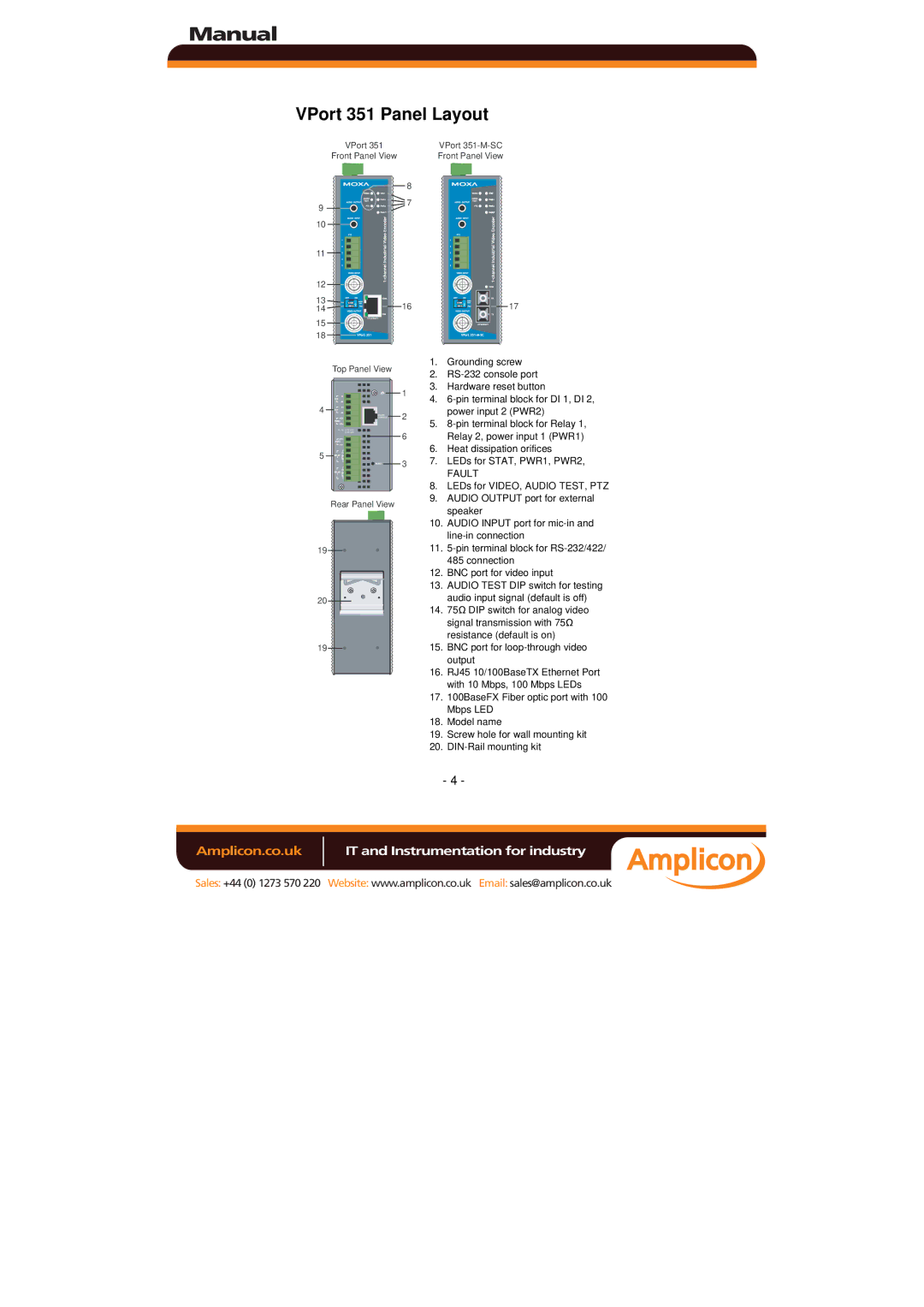
VPort 351
Front Panel View
| 8 |
9 | 7 |
| |
10 |
|
11 |
|
12 |
|
13 | 16 |
14 | |
15 |
|
18 |
|
Top Panel View
|
|
| 1 |
4 |
| 2 | |
|
| CONSOLE | |
|
|
| |
| V1, V2: |
| 6 |
|
| ||
|
|
| |
5 |
|
| 3 |
|
|
|
Rear Panel View
19 |
20 |
19 |
VPort
Front Panel View
17 |
1.Grounding screw
2.
3.Hardware reset button
4.
5.
6.Heat dissipation orifices
7.LEDs for STAT, PWR1, PWR2,
FAULT
8.LEDs for VIDEO, AUDIO TEST, PTZ
9.AUDIO OUTPUT port for external speaker
10.AUDIO INPUT port for
11.
485 connection
12.BNC port for video input
13.AUDIO TEST DIP switch for testing audio input signal (default is off)
14.75Ω DIP switch for analog video signal transmission with 75Ω resistance (default is on)
15.BNC port for
16.RJ45 10/100BaseTX Ethernet Port with 10 Mbps, 100 Mbps LEDs
17.100BaseFX Fiber optic port with 100 Mbps LED
18.Model name
19.Screw hole for wall mounting kit
20.
- 4 -
Amplicon.co.uk | IT and Instrumentation for industry |
Sales: +44 (0) 1273 570 220 Website: www.amplicon.co.uk Email: sales@amplicon.co.uk