2.Move the Voltage Selector (Figure 9) to the desired position.
operation
FRONT
3PHASE 240/139
3 PHASE | 1 PHASE |
480/277 | 240/120 |
PRESS TO LOCK
Figure 9. Voltage Selector Positions
3.Adjust the Voltage Regulator Knob to the corresponding voltage noted in Table 3. Check the AC voltmeter for the correct reading. See Figure 10.
INCREASEDECREASE
AC Voltmeter | Voltage Regulator |
Figure 10. Voltage Regulator Knob and AC
Voltmeter
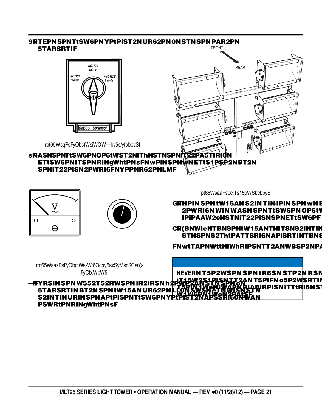
4.Switch the appropriate circuit breakers to the ON position for the lamps (Figure 11) that you want to turn on (in the selected Voltage Selector setting), as detailed in Table 3.
REAR
LAMP 1
LAMP 4
LAMP 2 ![]()
![]()
![]()
LAMP 5
LAMP 3
LAMP 6
MAST RAISED
Figure 11. Lamp Orientation
5.When the lamps turn on, check the AC voltmeter reading and adjust the Voltage Regulator knob, if necessary, to correct the voltage.
6.If any of the lamps do not turn on as they should, refer to the troubleshooting section of this manual.
7.Close all cabinet doors after desired lights are on.
![]() NOTICE
NOTICE
NEVER operate the light tower with the engine compartment doors open. Operation with the doors open may cause insufficient cooling to the unit, and damage may result.
MLT25 SERIES LIGHT TOWER • operation manual — rev. #0 (11/28/12) — page 21