Engine Startup

Speed Control Lever

1.Set the Speed Control Lever (Figure 10) to a position half way between start and stop.

Figure 10. Speed Control Lever

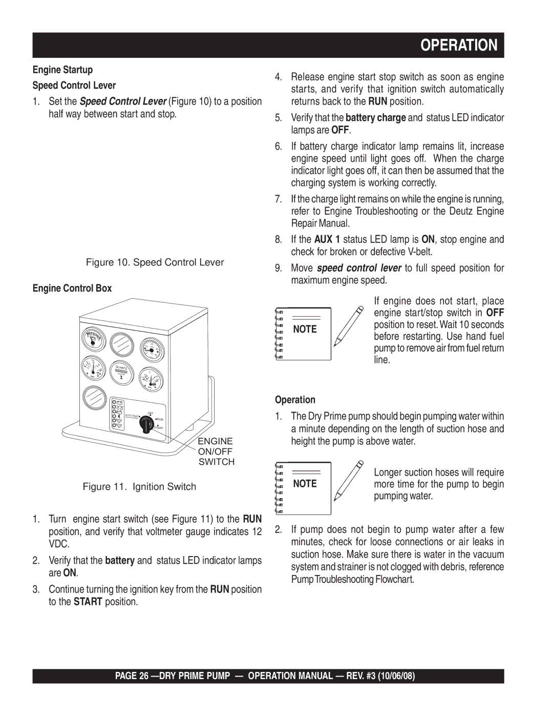
Engine Control Box

8

10 12

14


16


VDO


10

20


RPM


30


0

x100


40


VDO


20


PSI


40


0


60

80

QUARTZ


0

2

3


1


4


bar

5


0 0

0 2 5

5


HOURS


F


VDO


200


260


120


90

120

300


50

C

150


VDO


AUTO

START

OFF


(WHEN


0


AUX


EQUIPPED)

P

RUN


1


AUX


I

II

START


2


ENGINE

ON/OFF

SWITCH

Figure 11. Ignition Switch

1.Turn engine start switch (see Figure 11) to the RUN position, and verify that voltmeter gauge indicates 12 VDC.

2.Verify that the battery and status LED indicator lamps are ON.

3.Continue turning the ignition key from the RUN position

to the START position.

OPERATION

4.Release engine start stop switch as soon as engine starts, and verify that ignition switch automatically returns back to the RUN position.

5.Verify that the battery charge and status LED indicator lamps are OFF.

6.If battery charge indicator lamp remains lit, increase engine speed until light goes off. When the charge indicator light goes off, it can then be assumed that the charging system is working correctly.

7.If the charge light remains on while the engine is running, refer to Engine Troubleshooting or the Deutz Engine Repair Manual.

8.If the AUX 1 status LED lamp is ON, stop engine and check for broken or defective V-belt.

9.Move speed control lever to full speed position for maximum engine speed.

If engine does not start, place engine start/stop switch in OFF

NOTE position to reset. Wait 10 seconds before restarting. Use hand fuel pump to remove air from fuel return line.

Operation

1.The Dry Prime pump should begin pumping water within a minute depending on the length of suction hose and height the pump is above water.

Longer suction hoses will require

NOTE more time for the pump to begin pumping water.

2.If pump does not begin to pump water after a few minutes, check for loose connections or air leaks in suction hose. Make sure there is water in the vacuum system and strainer is not clogged with debris, reference PumpTroubleshooting Flowchart.

PAGE 26 —DRY PRIME PUMP — OPERATION MANUAL — REV. #3 (10/06/08)

Page 26
Image 26
Multiquip MP200SDLTE, MP200DLTE, MP150SDLTS, MP150SDLTE Operation, To the Start position, Longer suction hoses will require

MP200SDLTE, P200DLST, MP150SDLSM, MP200DLTS, MP200DLSM specifications

The Multiquip MP series of vibratory plate compactors, including models MP200DLTS, MP200DLTE, MP150SDLTE, P200DLST, and MP200SDLTE, are engineered for exceptional performance in compaction tasks across a variety of applications. These models are vital for contractors seeking efficiency, power, and reliability in the field.

The MP200DLTS and MP200DLTE models are particularly noteworthy for their robust design and versatility. Both are equipped with a powerful engine that delivers high centrifugal force, allowing operators to achieve effective compaction on different soil types. Their durable construction ensures longevity, even in demanding environments. The MP200DLTS features a dual-direction capability for increased maneuverability, while the MP200DLTE is designed for heavier-duty tasks and larger areas.

For users looking for a slightly more compact solution, the MP150SDLTE is a standout choice. This model combines portability with power, making it ideal for smaller jobs or confined spaces. It excels in providing precise compaction where larger equipment may struggle, while still maintaining high performance standards.

The P200DLST model offers enhanced features such as a heavy-duty baseplate designed to offer increased stability and excellent surface contact. This contributes to better results when compacting asphalt or granular materials, making it a preferred choice for road construction and repair projects.

Finally, the MP200SDLTE boasts advanced technology that enriches its operational capabilities. With an integrated vibration control system, users can adjust the compaction force on the fly, allowing for tailored performance based on specific job requirements. Its ergonomic handle design enhances user comfort, reducing fatigue during extended use.

Safety is also a priority in these models, with features such as protective guards and emergency stop buttons, ensuring that operators can work confidently. The overall combination of power, versatility, and innovative features makes the Multiquip MP series an essential tool for contractors in both construction and landscaping sectors.

In summary, whether it’s the heavy-duty capabilities of the MP200 series or the compact efficiency of the MP150SDLTE, Multiquip's offerings deliver outstanding performance, making them ideal for various compaction tasks. The robust engineering and thoughtful features provide users with the reliability needed in today’s competitive marketplace.