“SINGLE”, “SIDE BY SIDE1~3” and “PICTURE IN PICTURE (BOTTOM LEFT~TOP LEFT)”.
•Use the ▲ and ▼ buttons to select “MAIN”/ “SUB” and “LEFT”/“RIGHT”, then use the ◀ and ▶ buttons to choose from “VIDEO1~3”, “HD/DVD1~2” and “RGB/PC1~3”.
PROGRAM TIMER
DATE |
| ON | OFF | INPUT | FUNCTION |
MON | 08 : 30 | 10 : 30 | MULTI | INVERSE | |
TUE - | 18 : 15 | — | — | ||
SAT | 08 | : 30 | 12 : 15 | VIDEO1 | WHITE |
*FRI 08 : 30 | 10 : 00 | HD/DVD1 | — | ||
— | - | - | — | — | |
SAT | 08 : 30 | 12 : 15 | VIDEO1 | WHITE | |
* | 15 : 30 | 16 : 00 | RGB1 | — | |
SEL. | ZOOM ADJ. | EXIT RETURN | |||
PICTURE IN PICTURE | SIDE BY SIDE | ||||
PROGRAM TIMER | PROGRAM TIMER | ||||
MULTI SCREEN SETTING | MULTI SCREEN SETTING | ||||
MULTI MODE |
|
| MULTI MODE |
|
|
: BOTTOM LEFT |
|
| : SIDE BY SIDE1 |
|
|
INPUT MODE |
|
| INPUT MODE |
|
|
MAIN | : | RGB/PC1 | LEFT | : | RGB/PC1 |
SUB | : | VIDEO1 | RIGHT | : | VIDEO1 |
SEL. ADJ. |
| EXIT RETURN | SEL. ADJ. |
| EXIT RETURN |
MULTI REPEAT
Two repeat timers are available.
Each timer has MULTI MODE, WORK TIME and INPUT MODE functions.
Example:
TIMER1 is set to display RGB/PC1 (MAIN) and VIDEO1 (SUB) for 4 hours in
On “MULTI REPEAT” of “TIMER”, select “ON”, then press the MENU/ENTER button.
The “MULTI REPEAT TIMER” screen appears. Adjust the items.
|
| T I M E R |
|
| MULTI REPEAT TIMER | ||
PRESENT TIME |
|
| 1 MULTI MODE | : | BTM LFT | ||
PROGRAM |
| : | OFF | WORK TIME | : | 04H00M | |
MULTI REPEAT | : | OFF | INPUT MODE |
|
| ||
|
|
|
| MAIN |
| : | RGB/PC1 |
|
|
|
| SUB |
| : | VIDEO1 |
SEL. | ADJ. |
| EXIT RETURN | 2 MULTI MODE | : | S BY S1 | |
|
|
|
| WORK TIME | : | 02H30M | |
|
|
|
| INPUT MODE |
|
| |
|
|
|
| LEFT |
| : | RGB/PC3 |
|
|
|
| RIGHT | : | HD/DVD1 | |
|
|
|
| SEL. | ADJ. |
| EXIT RETURN |
Information
⬛MULTI REPEAT settings
MULTI MODE: Set the input mode to be displayed while the timer is on.
WORK TIME: Set the time duration of the display. Time range is from 1 minutes to 4 hours and 15 minutes. INPUT MODE: Set the signal that will be displayed within the selected screen.
Select “MAIN” or “SUB” for “PICTURE IN PICTURE (BTM LFT~TOP LFT)” and “LEFT” or “RIGHT” for “S BY S1~3”. Only one signal is selected for “SINGLE”.
*The two repeat timers run consecutively, i.e., Timer1–
*When both PROGRAM TIMER and MULTI REPEAT TIMER are set, priority is given to PROGRAM TIMER.
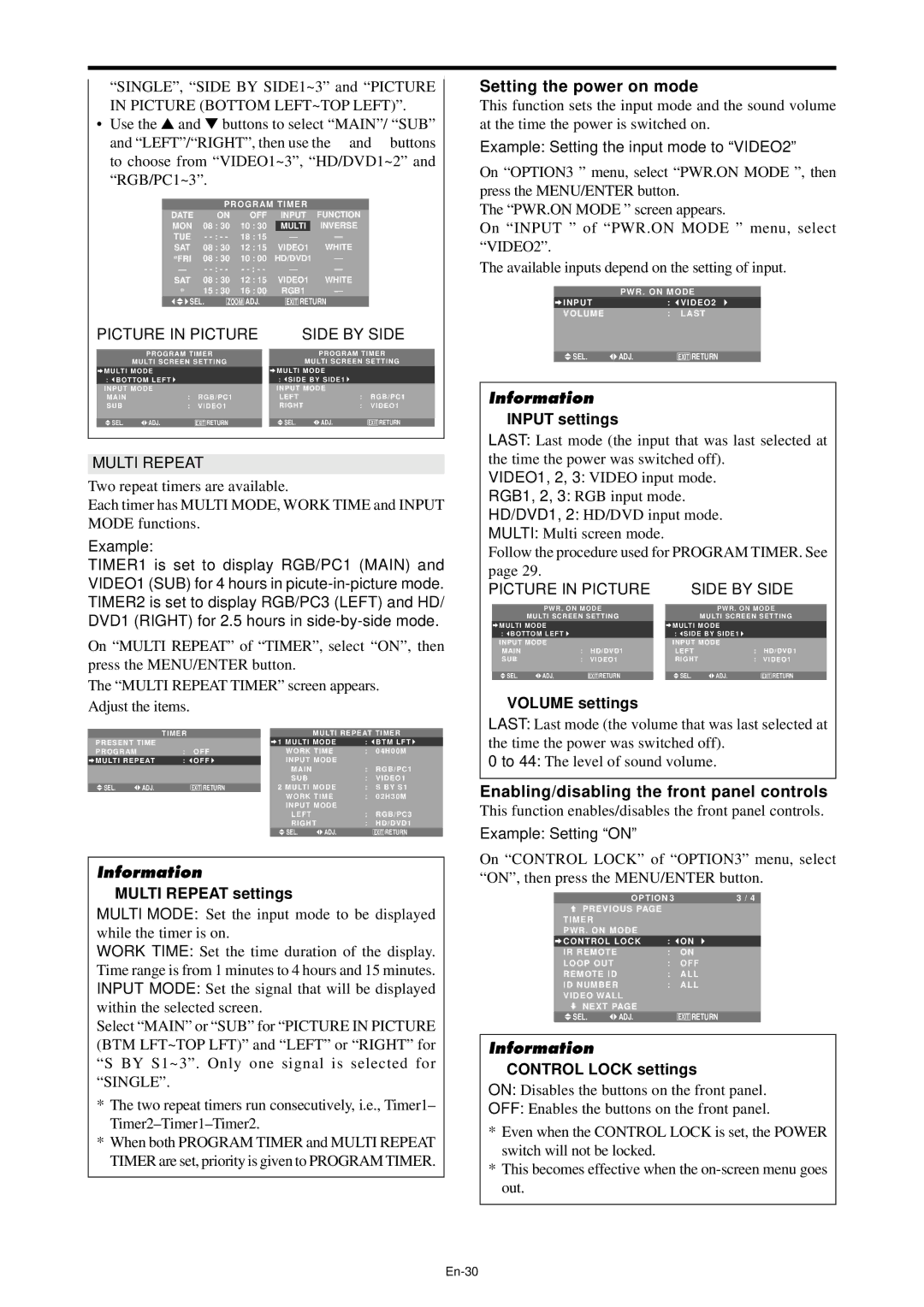
Setting the power on mode
This function sets the input mode and the sound volume at the time the power is switched on.
Example: Setting the input mode to “VIDEO2”
On “OPTION3 ” menu, select “PWR.ON MODE ”, then press the MENU/ENTER button.
The “PWR.ON MODE ” screen appears.
On “INPUT ” of “PWR.ON MODE ” menu, select “VIDEO2”.
The available inputs depend on the setting of input.
PWR . ON MODE
INPUT |
| : | VIDEO2 |
VOLUME |
| : | LAST |
|
|
|
|
SEL. | ADJ. |
| EXIT RETURN |
Information
⬛INPUT settings
LAST: Last mode (the input that was last selected at the time the power was switched off).
VIDEO1, 2, 3: VIDEO input mode.
RGB1, 2, 3: RGB input mode.
HD/DVD1, 2: HD/DVD input mode.
MULTI: Multi screen mode.
Follow the procedure used for PROGRAM TIMER. See
page 29. |
|
|
|
|
|
PICTURE IN PICTURE | SIDE BY SIDE | ||||
|
| ||||
PWR . ON MODE | PWR . ON MODE | ||||
MULTI SCREEN SETTING | MULTI SCREEN SETTING | ||||
MULTI MODE |
|
| MULTI MODE |
|
|
: BOTTOM LEFT |
|
| : SIDE BY SIDE1 |
|
|
INPUT MODE |
|
| INPUT MODE |
|
|
MAIN | : | HD/DVD1 | LEFT | : | HD/DVD1 |
SUB | : | VIDEO1 | RIGHT | : | VIDEO1 |
|
|
|
|
|
|
SEL. ADJ. |
| EXIT RETURN | SEL. ADJ. |
| EXIT RETURN |
⬛VOLUME settings
LAST: Last mode (the volume that was last selected at the time the power was switched off).
0 to 44: The level of sound volume.
Enabling/disabling the front panel controls
This function enables/disables the front panel controls.
Example: Setting “ON”
On “CONTROL LOCK” of “OPTION3” menu, select “ON”, then press the MENU/ENTER button.
OPTION 3 | 3 / 4 | |
PREVIOUS PAGE |
|
|
TIMER |
|
|
PWR . ON MODE |
|
|
CONTROL LOCK | : | ON |
IR REMOTE | : | ON |
LOOP OUT | : | OFF |
REMOTE ID | : | ALL |
ID NUMBER | : | ALL |
VIDEO WALL
NEXT PAGE
SEL. | ADJ. | EXIT RETURN |
Information
⬛CONTROL LOCK settings
ON: Disables the buttons on the front panel.
OFF: Enables the buttons on the front panel.
*Even when the CONTROL LOCK is set, the POWER switch will not be locked.
*This becomes effective when the