Vehicle Installation
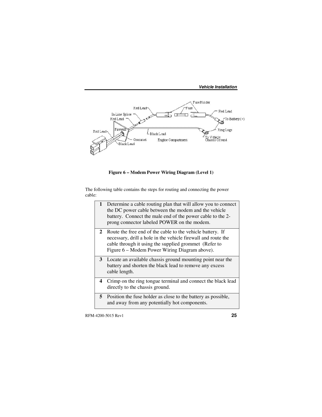
Figure 6 – Modem Power Wiring Diagram (Level 1)
The following table contains the steps for routing and connecting the power cable:
1Determine a cable routing plan that will allow you to connect the DC power cable between the modem and the vehicle battery. Connect the male end of the power cable to the 2- prong connector labeled POWER on the modem.
2Route the free end of the cable to the vehicle battery. If necessary, drill a hole in the vehicle firewall and route the cable through it using the supplied grommet (Refer to Figure 6 – Modem Power Wiring Diagram above).
3Locate an available chassis ground mounting point near the battery and shorten the black lead to remove any excess cable length.
4Crimp on the ring tongue terminal and connect the black lead directly to the chassis ground.
5Position the fuse holder as close to the battery as possible, and away from any potentially hot components.
25 |