iR1200 Modem
6Mount the fuse holder by tie wrapping it to the other cabling wires and dress wires as necessary.
7Shorten the red lead of the DC power cable to remove any excess length and crimp the fuse holder’s red lead to it using the
8Connect the ring tongue terminal from the fuse holder to the positive (+) battery terminal.
Route and Connect Ignition Cable
Approved Cable
The following DC power cable must be used (sold separately, see Accessories Table for ordering information).
5100-C5-RFM – Vehicle Power Harness
Route Cable
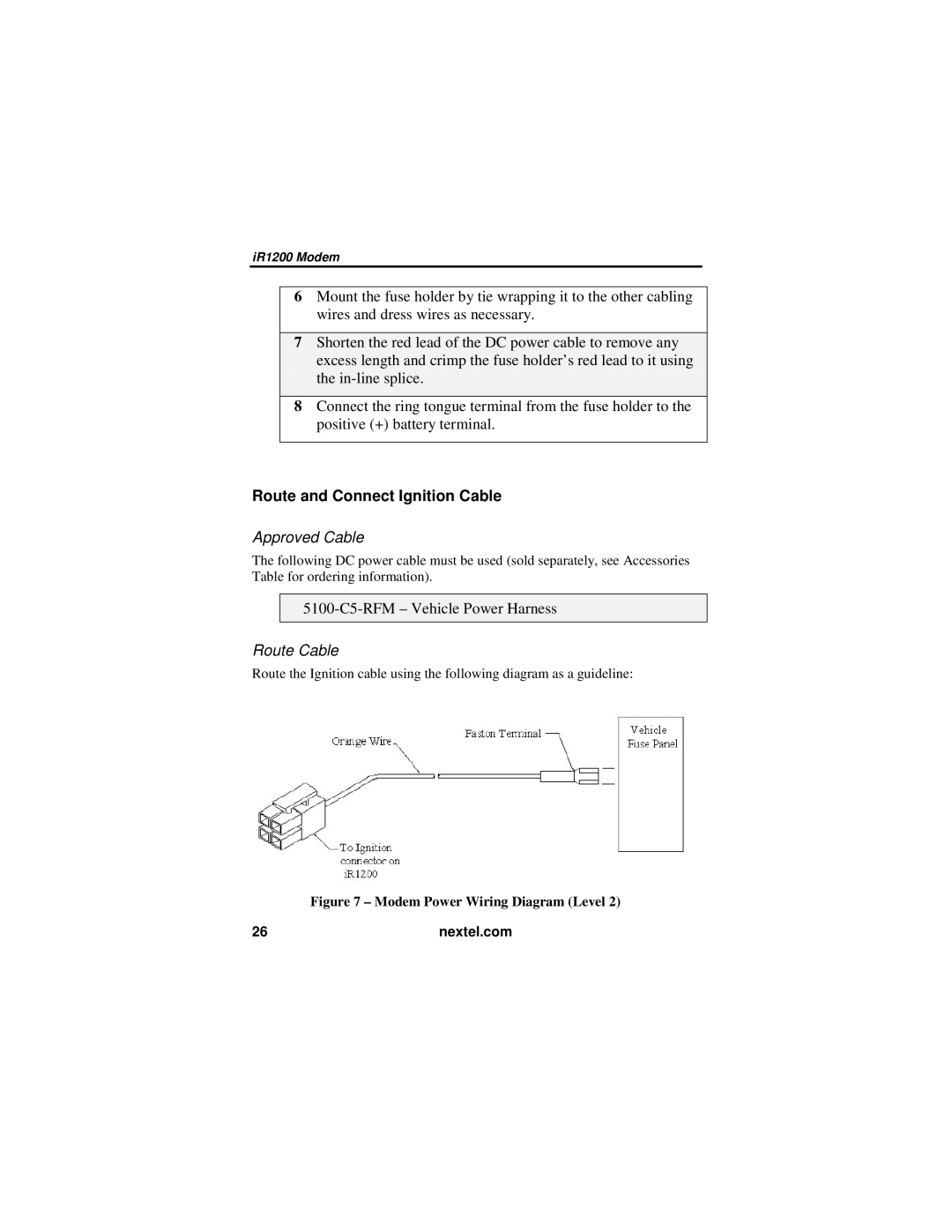
Route the Ignition cable using the following diagram as a guideline:
Figure 7 – Modem Power Wiring Diagram (Level 2)
26 | nextel.com |