1.7.5 Examples
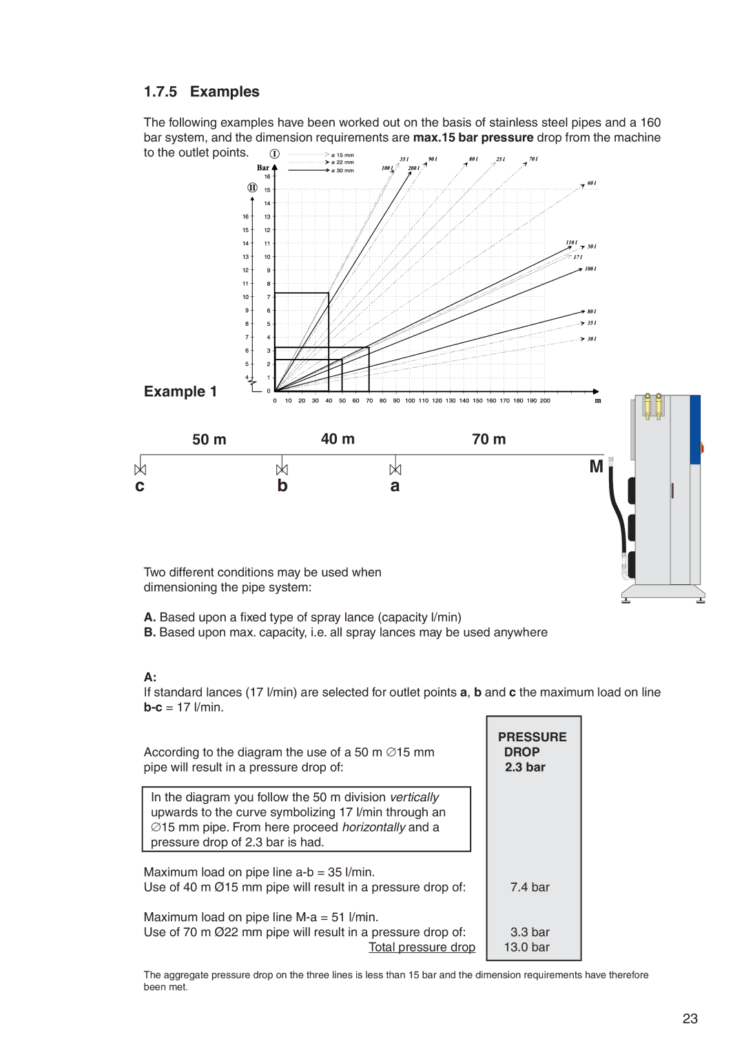
The following examples have been worked out on the basis of stainless steel pipes and a 160 bar system, and the dimension requirements are max.15 bar pressure drop from the machine to the outlet points. ![]()
![]()
![]()
Example 1 |
|
|
50 m | 40 m | 70 m |
|
| M |
c | b | a |
Two different conditions may be used when dimensioning the pipe system:
A. Based upon a fixed type of spray lance (capacity l/min)
B. Based upon max. capacity, i.e. all spray lances may be used anywhere
A:
If standard lances (17 l/min) are selected for outlet points a, b and c the maximum load on line
According to the diagram the use of a 50 m ∅15 mm pipe will result in a pressure drop of:
In the diagram you follow the 50 m division vertically upwards to the curve symbolizing 17 l/min through an ∅15 mm pipe. From here proceed horizontally and a pressure drop of 2.3 bar is had.
Maximum load on pipe line
Use of 40 m Ø15 mm pipe will result in a pressure drop of:
Maximum load on pipe line
Use of 70 m Ø22 mm pipe will result in a pressure drop of: Total pressure drop
PRESSURE DROP
2.3bar
7.4bar
3.3bar
13.0bar
The aggregate pressure drop on the three lines is less than 15 bar and the dimension requirements have therefore been met.
23