2.4Mains power connection between the DELTABOOSTER and the supply network (cf. Fig. 5)
All measurements and connections described below should be carried
out by authorized specialists !
1)The DELTABOOSTER should be connected to a
2)The connection should be established through a flexible rubber cable with 3 phase cores
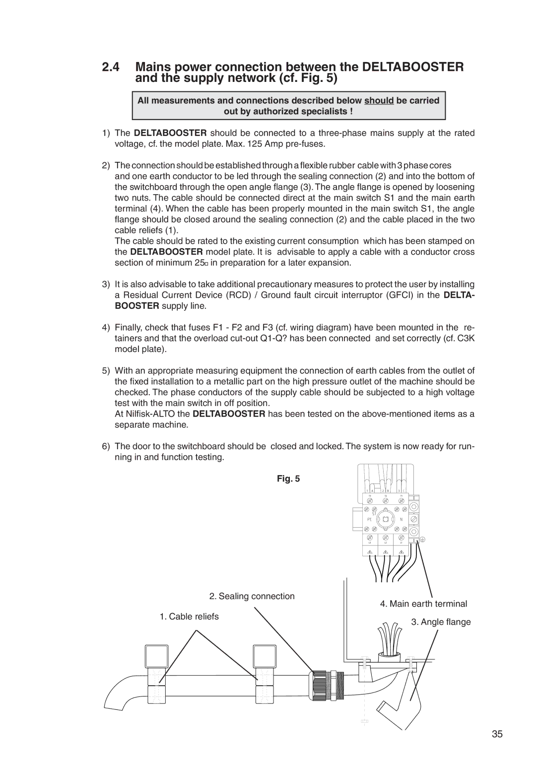
and one earth conductor to be led through the sealing connection (2) and into the bottom of the switchboard through the open angle flange (3). The angle flange is opened by loosening two nuts. The cable should be connected direct at the main switch S1 and the main earth terminal (4). When the cable has been properly mounted in the main switch S1, the angle flange should be closed around the sealing connection (2) and the cable placed in the two cable reliefs (1).
The cable should be rated to the existing current consumption which has been stamped on the DELTABOOSTER model plate. It is advisable to apply a cable with a conductor cross section of minimum 25![]() in preparation for a later expansion.
in preparation for a later expansion.
3)It is also advisable to take additional precautionary measures to protect the user by installing a Residual Current Device (RCD) / Ground fault circuit interruptor (GFCI) in the DELTA- BOOSTER supply line.
4)Finally, check that fuses F1 - F2 and F3 (cf. wiring diagram) have been mounted in the re- tainers and that the overload
5)With an appropriate measuring equipment the connection of earth cables from the outlet of the fixed installation to a metallic part on the high pressure outlet of the machine should be checked. The phase conductors of the supply cable should be subjected to a high voltage test with the main switch in off position.
At
6)The door to the switchboard should be closed and locked. The system is now ready for run- ning in and function testing.
Fig. 5
2.Sealing connection
1.Cable reliefs
4.Main earth terminal
3.Angle flange
35