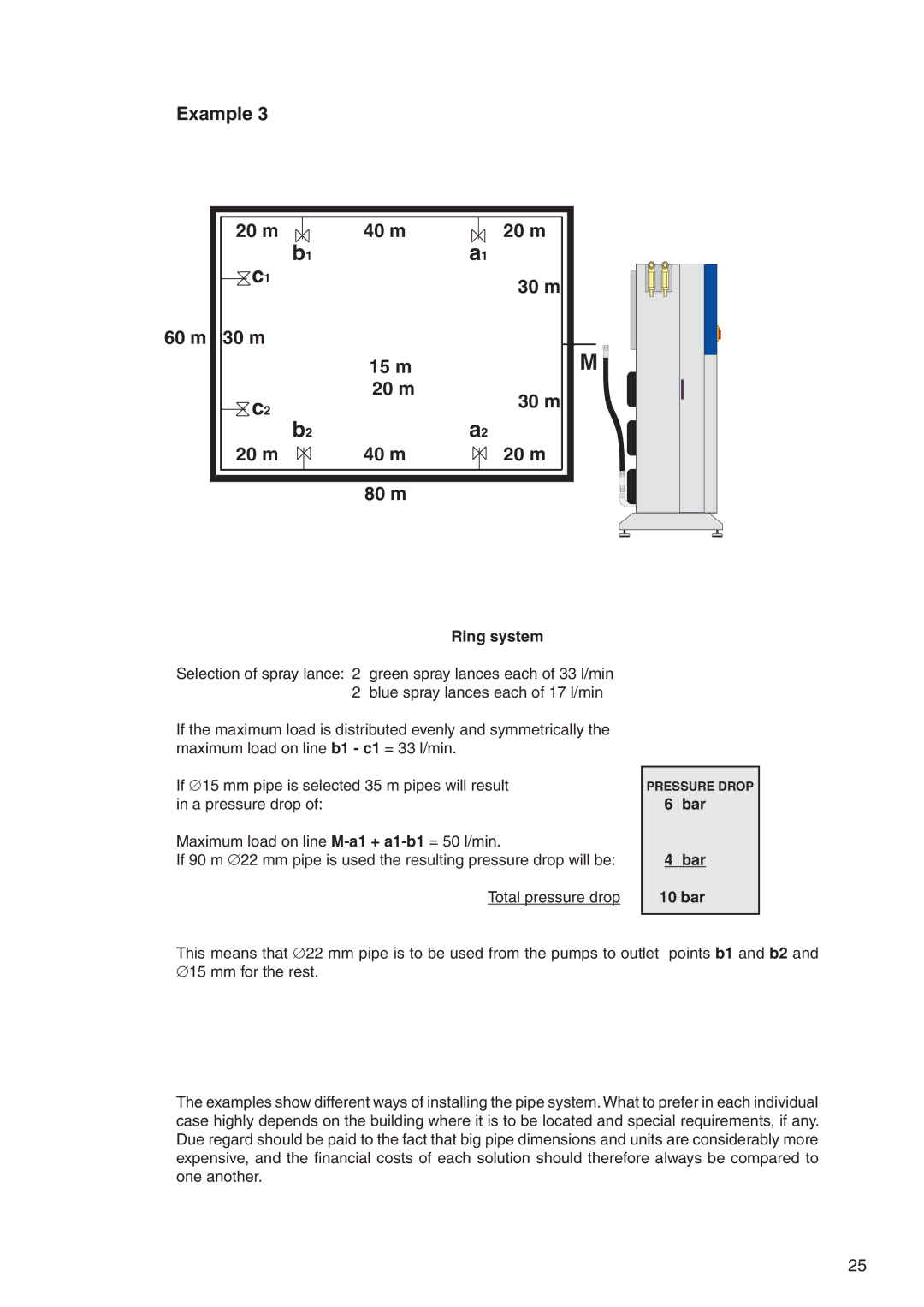
Example 3
20 m |
|
|
| 40 m |
|
|
|
| 20 m | |||
|
|
|
|
| ||||||||
|
|
| c1 | b1 | a1 | |||||||
|
|
|
|
|
|
|
|
|
|
| 30 m | |
|
|
|
|
|
|
|
|
|
|
| ||
|
|
|
|
|
|
|
|
|
|
| ||
|
|
|
|
|
|
|
|
|
|
|
| |
60 m 30 m
|
|
|
|
|
|
|
|
|
|
|
| 15 m |
|
|
|
|
|
|
|
|
|
|
| c2 |
|
|
|
|
|
| 20 m |
|
|
| 30 m | ||
|
|
|
|
|
|
|
|
|
|
|
|
|
|
| ||||
|
|
|
|
|
|
|
|
|
|
|
|
|
|
| ||||
|
|
|
|
|
|
|
|
|
|
|
|
|
|
| ||||
|
|
|
|
|
| b2 | a2 | |||||||||||
|
| 20 m |
|
|
|
|
|
| 40 m |
|
|
| 20 m | |||||
|
|
|
|
|
|
|
| |||||||||||
|
|
|
| |||||||||||||||
|
|
|
|
|
| |||||||||||||
|
|
|
|
|
|
|
|
|
|
|
|
|
|
|
|
|
|
|
|
|
|
|
|
|
|
|
|
|
|
|
|
|
|
|
|
|
|
|
|
|
|
|
|
|
|
|
|
|
|
|
|
|
|
|
|
|
|
|
|
|
|
|
|
|
|
|
|
| 80 m |
|
|
|
|
|
|
M ![]()
![]()
![]()
Ring system
Selection of spray lance: 2 green spray lances each of 33 l/min 2 blue spray lances each of 17 l/min
If the maximum load is distributed evenly and symmetrically the maximum load on line b1 - c1 = 33 l/min.
If ∅15 mm pipe is selected 35 m pipes will result in a pressure drop of:
Maximum load on line
If 90 m ∅22 mm pipe is used the resulting pressure drop will be:
Total pressure drop
PRESSURE DROP 6 bar
4bar
10 bar
This means that ∅22 mm pipe is to be used from the pumps to outlet points b1 and b2 and ∅15 mm for the rest.
The examples show different ways of installing the pipe system.What to prefer in each individual case highly depends on the building where it is to be located and special requirements, if any. Due regard should be paid to the fact that big pipe dimensions and units are considerably more expensive, and the financial costs of each solution should therefore always be compared to one another.
25
