3.4.3 The control panel
The control panel (5) is based upon a schematic drawing of the system where a number of control lamps will show the status of the system and possible faults.
The control lamps have been divided into three categories:
Green indicating a coupled unit (valve, C3K)
Yellow indicating an activated sensor (pressure switch, flow, level)
Red indicating a serious fault (leakage, over heating, etc.)
In normal conditions only the green and the yellow control lamps will glow.
If a serious fault arises the relevant red control lamp will start flashing and at the same time the system will stop operating completely. Status from the other lamps is retained so the condition at the moment of the fault is visible.
If a red control lamp flashes the system can usually not be
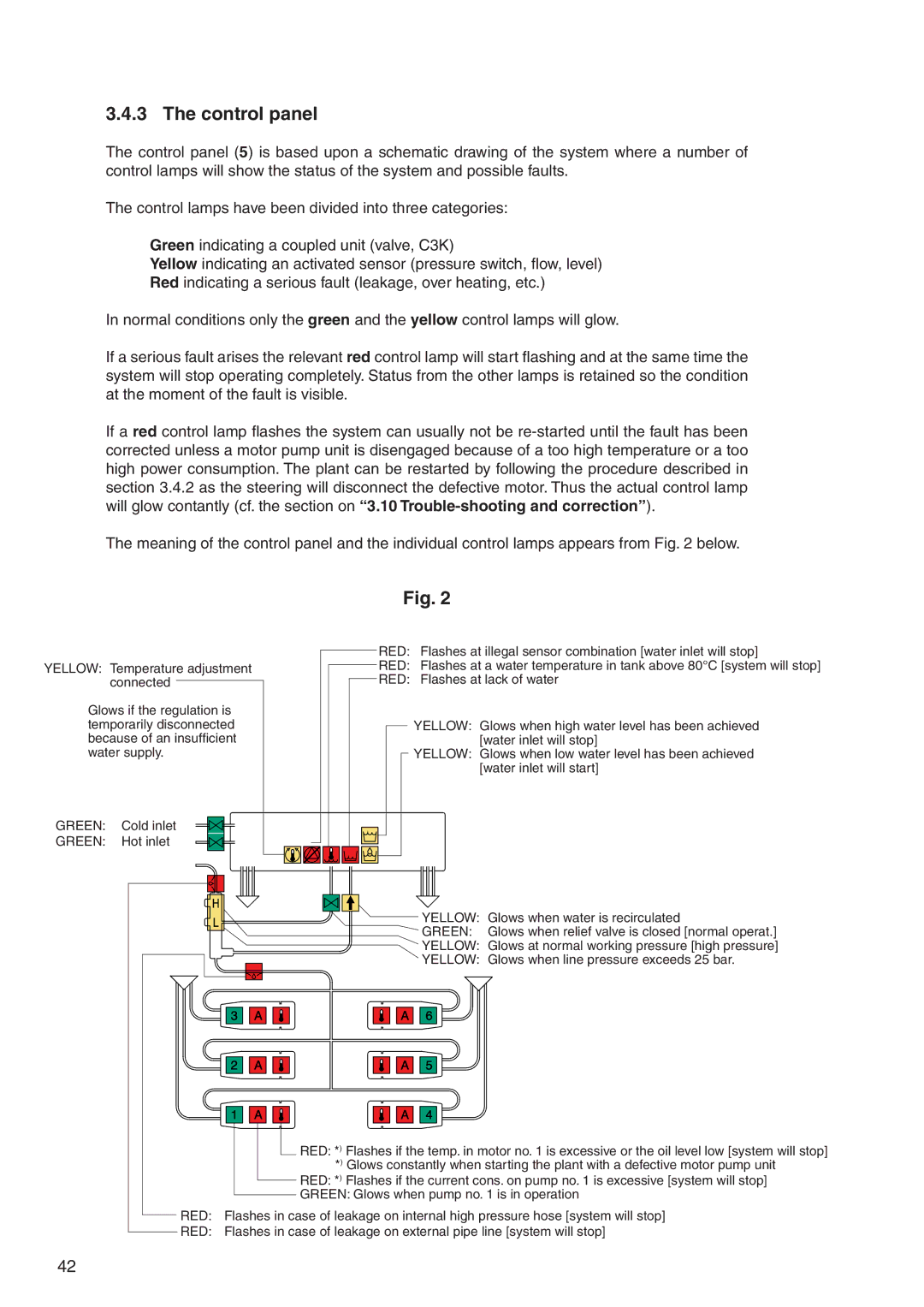
The meaning of the control panel and the individual control lamps appears from Fig. 2 below.
Fig. 2
|
| RED: Flashes at illegal sensor combination [water inlet will stop] | |
YELLOW: Temperature adjustment | RED: | Flashes at a water temperature in tank above 80°C [system will stop] | |
| connected | RED: | Flashes at lack of water |
Glows if the regulation is |
|
| |
temporarily disconnected |
| YELLOW: Glows when high water level has been achieved | |
because of an insufficient |
| [water inlet will stop] | |
water supply. |
| YELLOW: Glows when low water level has been achieved | |
|
|
| [water inlet will start] |
GREEN: | Cold inlet |
|
|
GREEN: | Hot inlet |
|
|
|
|
| YELLOW: Glows when water is recirculated |
|
|
| GREEN: Glows when relief valve is closed [normal operat.] |
|
|
| YELLOW: Glows at normal working pressure [high pressure] |
|
|
| YELLOW: Glows when line pressure exceeds 25 bar. |
![]() RED: *) Flashes if the temp. in motor no. 1 is excessive or the oil level low [system will stop]
RED: *) Flashes if the temp. in motor no. 1 is excessive or the oil level low [system will stop]
*) Glows constantly when starting the plant with a defective motor pump unit
RED: *) Flashes if the current cons. on pump no. 1 is excessive [system will stop]
GREEN: Glows when pump no. 1 is in operation
RED: Flashes in case of leakage on internal high pressure hose [system will stop]
RED: Flashes in case of leakage on external pipe line [system will stop]
42