1.7.4 Dimensioning of pipe systems
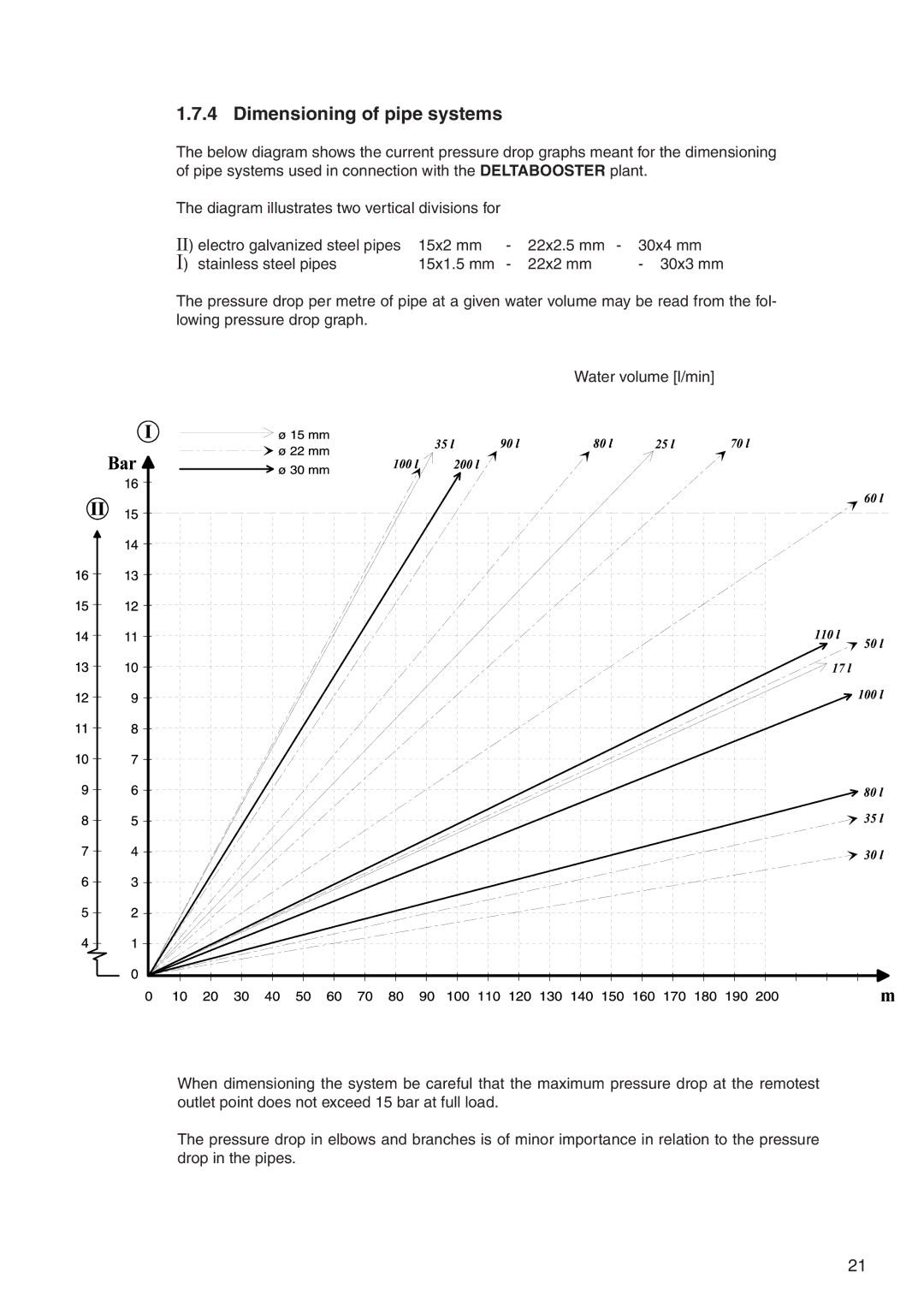
The below diagram shows the current pressure drop graphs meant for the dimensioning of pipe systems used in connection with the DELTABOOSTER plant.
The diagram illustrates two vertical divisions for |
|
|
| |
II) electro galvanized steel pipes | 15x2 mm | - | 22x2.5 mm - | 30x4 mm |
I) stainless steel pipes | 15x1.5 mm | - | 22x2 mm | - 30x3 mm |
The pressure drop per metre of pipe at a given water volume may be read from the fol- lowing pressure drop graph.
Water volume [l/min]
When dimensioning the system be careful that the maximum pressure drop at the remotest outlet point does not exceed 15 bar at full load.
The pressure drop in elbows and branches is of minor importance in relation to the pressure drop in the pipes.
21
