VII. Expanding Essentia to 12 Zones
Six additional listening zones can be added to the Essentia System using the Essentia Expander package. The expansion is easily done using the Source Link and Digital Link
The necessary cables for this are supplied with the Expander package. No other connections are necessary with the exception of the AC power cord and the additional speaker terminations. The additional CAT5 wires for the zones
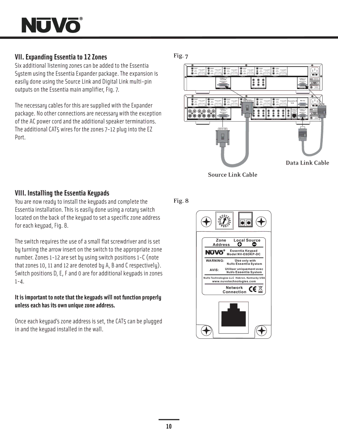
Fig. 7
VARIABLE | VARIABLE | VARIABLE | VARIABLE | VARIABLE |
| VARIABLE |
OUTPUT | OUTPUT | OUTPUT | OUTPUT | OUTPUT |
| OUTPUT |
OUTPUT POWER | OUTPUT POWER | OUTPUT POWER | OUTPUT POWER |
| OUTPUT POWER | OUTPUT POWER |
TIP=L | TIP=L | TIP=L | TIP=L | TIP=L |
| TIP=L |
RING=R | RING=R | RING=R | RING=R | RING=R |
| RING=R |
FIXED | FIXED | FIXED | FIXED | FIXED |
| FIXED |
OUTPUT | OUTPUT | OUTPUT | OUTPUT | OUTPUT |
| OUTPUT |
ZONE 71 | ZONE 8 | ZONE 9 | ZONE 10 | ZONE 11 |
| ZONE 12 |
| CONNECT TO | 7 | 8 | 9 |
| |
| 1 |
|
| CONNECT TO | ||
|
|
|
| |||
|
| USE |
|
|
|
|
|
| USE | |
|
|
| CABLE |
|
|
|
|
|
| CABLE |
|
|
|
| 5 | 10 | 11 | 12 |
|
|
|
|
| SOURCE LINK |
| ZONE TRIGGER OUTPUTS |
|
| DIGITAL LINK | |||
VARIABLE | VARIABLE |
| VARIABLE | VARIABLE |
|
| VARIABLE | VARIABLE |
|
|
OUTPUT | OUTPUT |
| OUTPUT | OUTPUT |
|
| OUTPUT | OUTPUT | Essentia D |
|
TIP=L OUTPUT POWER | TIP=L | OUTPUT POWER | TIP=L OUTPUT POWER | TIP=L OUTPUT POWER |
| TIP=L OUTPUT POWER | TIP=L OUTPUT POWER | |||
RING=R | RING=R |
| RING=R | RING=R |
|
| RING=R | RING=R | V.II |
|
FIXED | FIXED |
| FIXED | FIXED |
|
| FIXED | FIXED |
| |
OUTPUT | OUTPUT |
| OUTPUT | OUTPUT |
|
| OUTPUT | OUTPUT |
|
|
| ZONE 1 |
|
| ZONE 2 |
| ZONE 3 | ZONE 4 |
| ZONE 5 |
|
| ZONE 6 |
|
|
| PROGRAM |
1 | 2 | 3 | 4 | 5 | 6 | CONNECT TO |
| 1 | 2 | 3 | 1 | 2 | 3 | SUM1 | SYS ON |
|
|
|
|
|
|
| 1 |
|
|
|
|
|
|
| CONNECT TO | CONNECT TO | |
|
|
|
|
|
|
|
|
|
|
|
|
|
|
USE | USE | USE |
CABLE | ||
CABLE |
| CABLE |
1 | 2 | 3 | 4 | 5 | 6 | 5 | 4 | 5 | 6 | 4 | 5 | 6 | SUM2 | EXT. MUTE |
|
|
|
| SOURCE INPUTS |
| SOURCE LINK |
| ZONE TRIGGER OUTPUTS |
| EMITTER OUTPUTS |
| SYSTEM | NETWORK | DIGITAL LINK | ||||
Data Link Cable
Source Link Cable
VIII. Installing the Essentia Keypads
You are now ready to install the keypads and complete the | Fig. 8 |
Essentia installation. This is easily done using a rotary switch |
|
located on the back of the keypad to set a specific zone address |
|
for each keypad, Fig. 8. |
|
The switch requires the use of a small flat screwdriver and is set |
|
by turning the arrow insert on the switch to the appropriate zone |
|
number. Zones |
|
that zones 10, 11 and 12 are denoted by A, B and C respectively). |
|
Switch positions D, E, F and 0 are for additional keypads in zones |
|
|
It is important to note that the keypads will not function properly unless each has its own unique zone address.
Once each keypad’s zone address is set, the CAT5 can be plugged in and the keypad installed in the wall.
| 0 |
|
|
| F 1 |
| |
D | E | 2 | |
3 | |||
| 4 | ||
C |
| 5 | |
B | 7 | 6 | |
|
|
| |
| A98 |
| |
Zone |
| Local Source | |
Address | |||
|
|
| Essentia Keypad |
|
| Model | |
WARNING: |
| Use only with | |
| NuVo Essentia System | |
AVIS: | Utiliser uniquement avec | |
NuVo Essentia System | ||
|
NuVo Technologies LLC Hebron, Kentucky USA
www.nuvotechnologies.com
Network
Connection
10