E Series Amplifier Back Panel
| ZONE 1 |
|
| ZONE 2 |
| ||
L | R | LEFT | RIGHT | L | R | LEFT | RIGHT |
|
| - + | - + |
|
| - + | - + |
LINE OUT | 20W/8 OHM X2 | LINE OUT | 20W/8 OHM X2 | ||||
|
|
|
| ||||
INPUT SOURCES
L
R
1 2 3 4 5 6
| ZONE 3 |
|
| ZONE 4 |
| ||
L | R | LEFT | RIGHT | L | R | LEFT | RIGHT |
|
| - + | - + |
|
| - + | - + |
LINE OUT | 20W/8 OHM X2 | LINE OUT | 20W/8 OHM X2 | ||||
|
|
|
| ||||
AUDIO OUTPUT
CONNECT TO
|
|
|
|
|
|
|
| DIAGNOSTIC | CONTROL | |||
| ZONE 5 |
|
| ZONE 6 |
|
|
|
|
|
| ||
L | R | LEFT | RIGHT | L | R | LEFT | RIGHT | REFER TO MANUAL MUTE UNIT ON | ||||
|
| - + | - + |
|
| - + | - + |
|
|
|
|
|
|
|
|
|
|
|
|
| 0 | 1 | 2 | 3 | N.O. G +12V G |
|
|
|
|
|
|
|
|
| ||||
LINE OUT | 20W/8 OHM X2 | LINE OUT | 20W/8 OHM X2 |
|
|
|
| |||||
|
|
|
|
|
|
|
| |||||
|
|
| IR EMITTER OUTPUTS |
|
| NETWORK |
|
| DIGITAL OUTPUT | |||
|
| +12V OUTPUT PULSE |
| CONNECT TO |
|
| CONNECT TO | |||||
|
|
|
|
|
|
|
|
|
|
| ||
ODD NUMBERED OUTPUTS ARE IDENTICAL (TIED TOGETHER)
EVEN NUMBERED OUTPUTS ARE IDENTICAL (TIED TOGETHER)
1 2 3 4 5 6 SUM
MODEL
SIX SOURCE SIX ZONE
AUDIO DISTRIBUTION SYSTEM
120V ![]() 60Hz 300W
60Hz 300W
KUSTOM INC. CINCINNATI, OH USA
0215 |
1 2 3
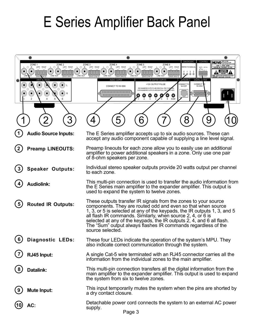
1Audio Source Inputs:
2Preamp LINEOUTS:
3Speaker Outputs:
4 Audiolink:
5Routed IR Outputs:
6Diagnostic LEDs:
7RJ45 Input:
8 Datalink:
9Mute Input:
10 AC:
4 | 5 | 6 | 7 | 8 | 9 | 10 |
The E Series amplifier accepts up to six audio sources. These can accept any audio component capable of supplying a line level signal.
Preamp lineouts for each zone allow you to easily use an additional amplifier to power additional speakers in a zone. Only use one pair of
Individual stereo speaker outputs provide 20 watts output per channel to each zone.
This
These outputs transfer IR signals from the zones to your source components. They are routed odd and even so that when source
1, 3, or 5 is selected at any of the keypads, the IR outputs 1, 3, and 5 all flash IR commands. Similarly, when source 2, 4, or 6 is selected at any of the keypads, the IR outputs 2, 4, and 6 all flash. The “Sum” output always flashes IR commands regardless of the source selected.
These four LEDs indicate the operation of the system’s MPU. They also indicate correct communication through the system.
A single
This
This input temporarily mutes the system when the pins are shorted by a dry contact closure.
Detachable power cord connects the system to an external AC power supply.
Page 3
