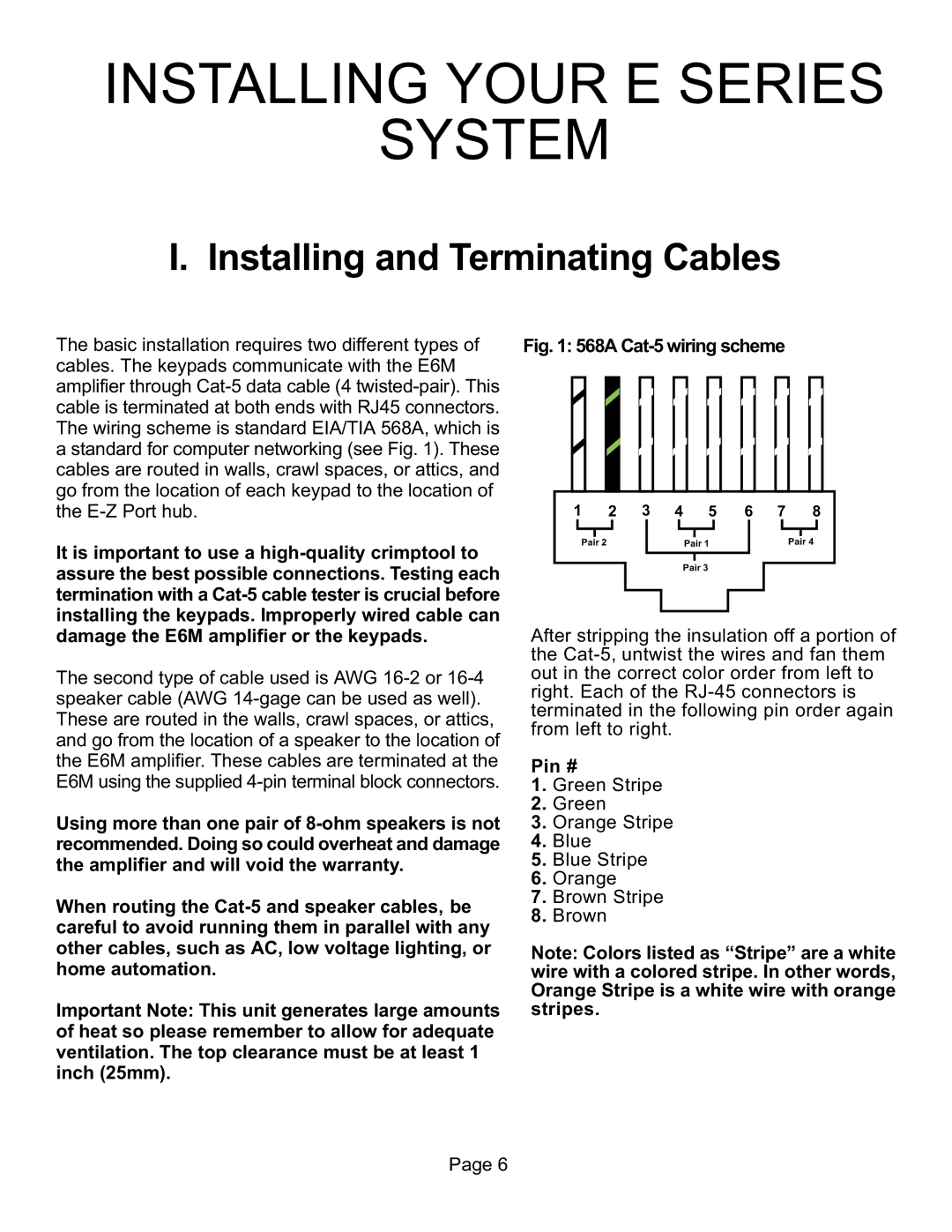
The basic installation requires two different types of cables. The keypads communicate with the E6M amplifier through Cat-5 data cable (4 twisted-pair). This cable is terminated at both ends with RJ45 connectors. The wiring scheme is standard EIA/TIA 568A, which is a standard for computer networking (see Fig. 1). These cables are routed in walls, crawl spaces, or attics, and go from the location of each keypad to the location of the E-Z Port hub.
It is important to use a high-quality crimptool to assure the best possible connections. Testing each termination with a Cat-5 cable tester is crucial before installing the keypads. Improperly wired cable can damage the E6M amplifier or the keypads.
The second type of cable used is AWG 16-2 or 16-4 speaker cable (AWG 14-gage can be used as well). These are routed in the walls, crawl spaces, or attics, and go from the location of a speaker to the location of the E6M amplifier. These cables are terminated at the E6M using the supplied 4-pin terminal block connectors.
Using more than one pair of 8-ohm speakers is not recommended. Doing so could overheat and damage the amplifier and will void the warranty.
When routing the Cat-5 and speaker cables, be careful to avoid running them in parallel with any other cables, such as AC, low voltage lighting, or home automation.
Important Note: This unit generates large amounts of heat so please remember to allow for adequate ventilation. The top clearance must be at least 1 inch (25mm).
Fig. 1: 568A Cat-5 wiring scheme
Pair 3
After stripping the insulation off a portion of the Cat-5, untwist the wires and fan them out in the correct color order from left to right. Each of the RJ-45 connectors is terminated in the following pin order again from left to right.
Pin #
1.Green Stripe
2.Green
3.Orange Stripe
4.Blue
5.Blue Stripe
6.Orange
7.Brown Stripe
8.Brown
Note: Colors listed as “Stripe” are a white wire with a colored stripe. In other words, Orange Stripe is a white wire with orange stripes.

