Installing and wiring telephones and trunks
Installing the 26B1 Selector Console
To install the 26B1 Selector Console:
1.Connect the supplied
2.Route the cable to the attendant console and connect to the DXS/BLF jack.
3.Attach labels according to the Attendant Console form.
4.Administer the console using Administrator Guide for Avaya Communication Manager
Connecting external alarm indicators and auxiliary power
Alarms can be generated on adjunct equipment, sent to the server, and recorded and reported as “external alarms.” A typical major alarm input is from an uninterruptible power supply (UPS).
The media gateway provides a relay contact that can operate a
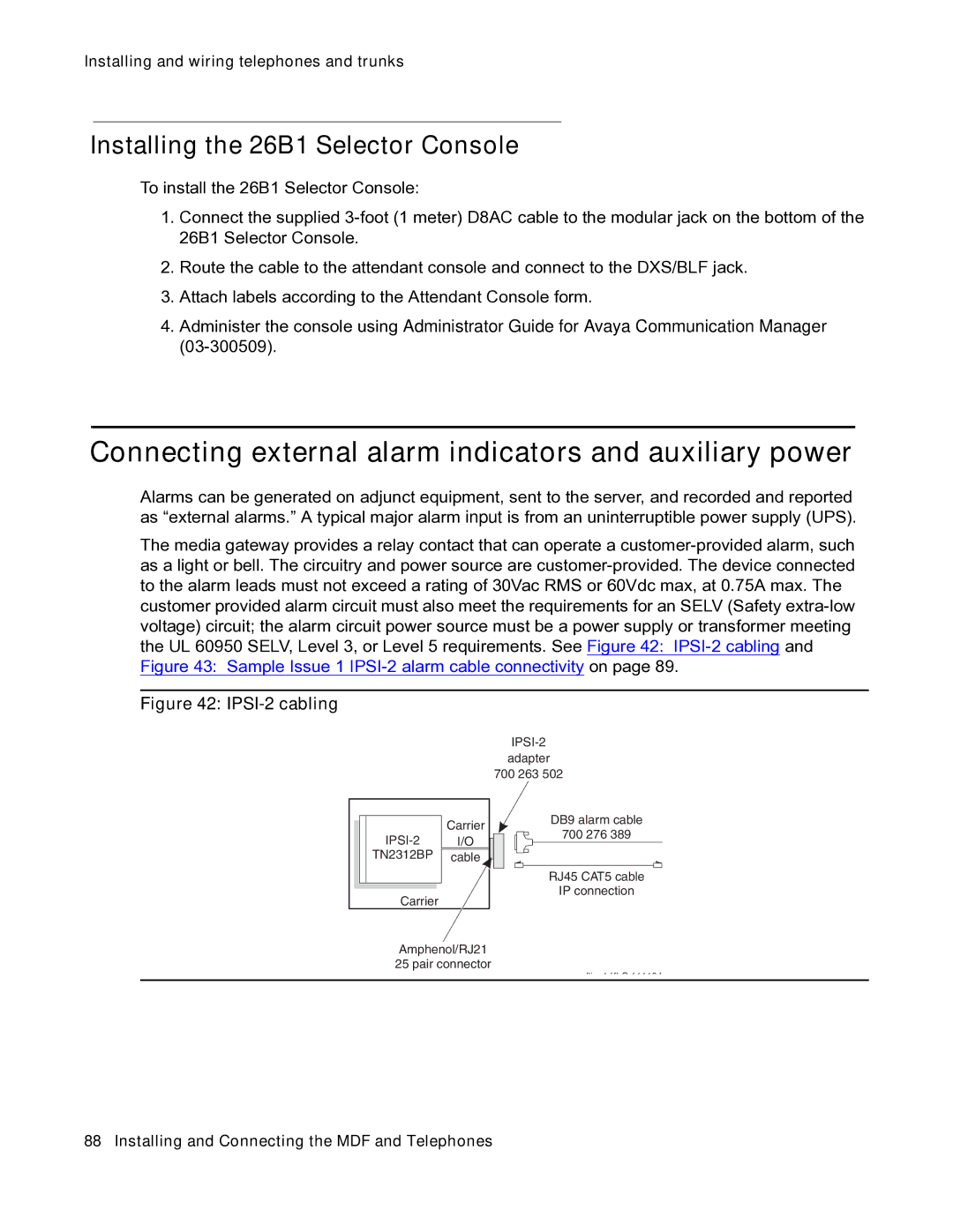
Figure 42: IPSI-2 cabling
adapter
700 263 502
| Carrier |
I/O | |
TN2312BP | cable |
Carrier |
|
DB9 alarm cable
700 276 389
RJ45 CAT5 cable
IP connection
Amphenol/RJ21 25 pair connector
dli 1 KLC 111104