Installing and administering the patch cord/jumper
Connecting trunk pairs to media gateway
using jumper wires to establish
Figure 32: 3-pair modularity for trunk pairs for 1-pair trunks on page 67 and Figure 33: 3-pair modularity for trunk pairs for 3-pair Tie trunks on page 68 show trunk pairs connected to the media gateway with jumper wires to establish 3-pair modularity.
To connect the trunk pairs to the purple field:
1.Connect B25A cables between the network interface and the sneak fuse panels. See Figure 32:
2.Connect A25D/B25A cables from the sneak fuse panels to the
3.Connect
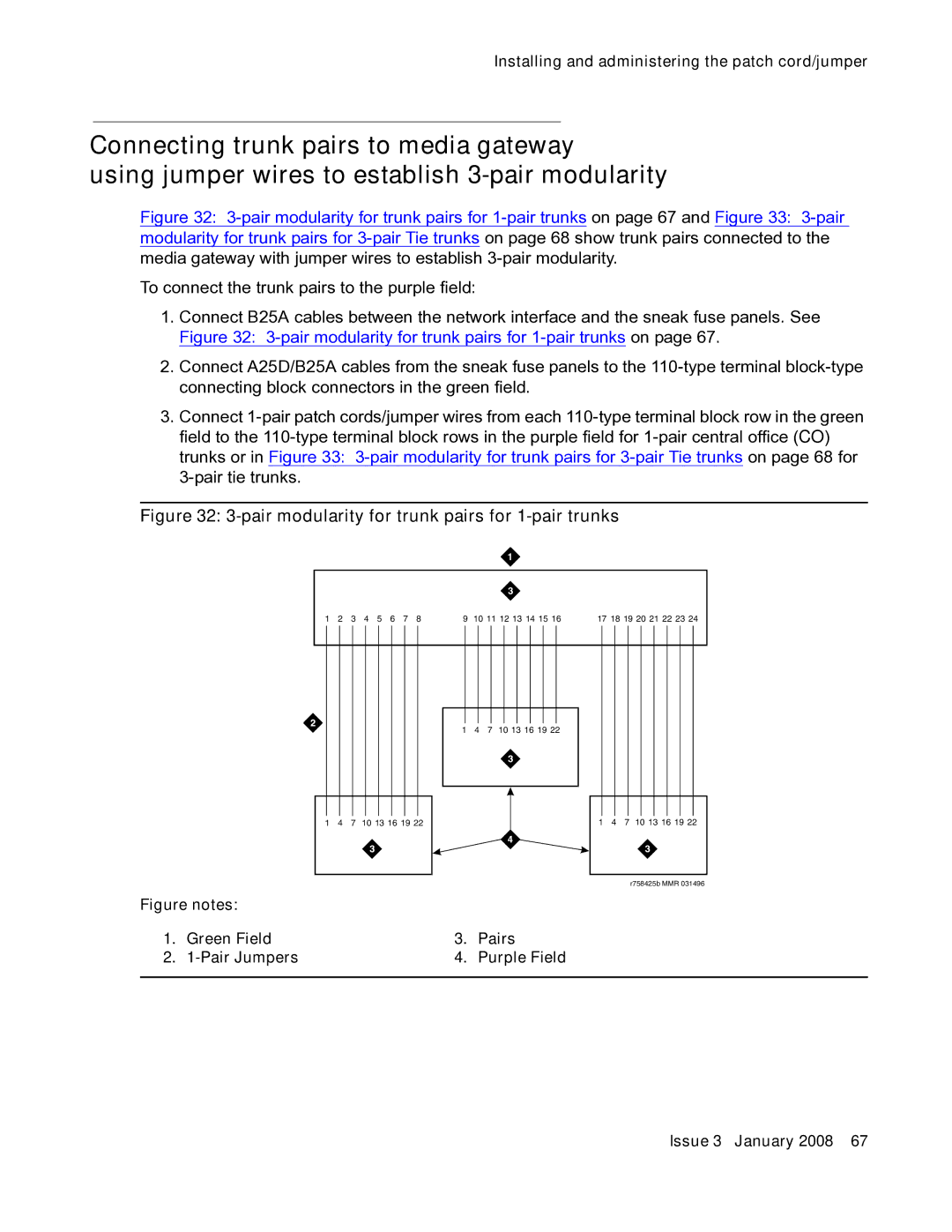
Figure 32: 3-pair modularity for trunk pairs for 1-pair trunks
1 | 2 | 3 | 4 | 5 | 6 | 7 | 8 | 9 | 10 11 12 13 14 15 16 | 17 18 19 20 21 22 23 24 |
1 4 7 10 13 16 19 22
1 | 4 | 7 | 10 13 16 19 22 | 1 | 4 | 7 | 10 13 16 19 22 |
r758425b MMR 031496
Figure notes: |
|
| |
1. | Green Field | 3. | Pairs |
2. |
| 4. | Purple Field |
|
|
|
|