Installing and wiring telephone power supplies
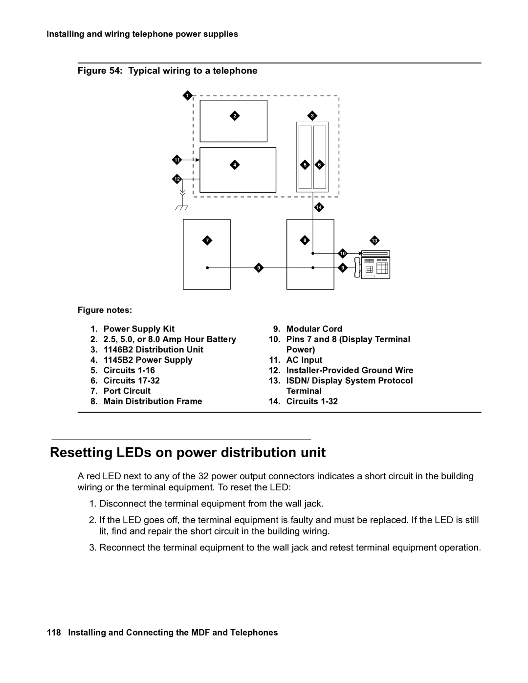
Figure 54: Typical wiring to a telephone
1
2 | 3 |
11 ![]()
4 | 5 | 146 |
12
|
| 14 |
7 | 8 | 13 |
|
| 10 |
9 |
| 9 |
Figure notes: |
|
|
| |
1. | Power Supply Kit | 9. | Modular Cord | |
2. | 2.5, 5.0, or 8.0 Amp Hour Battery | 10. | Pins 7 and 8 (Display Terminal | |
3. | 1146B2 | Distribution Unit |
| Power) |
4. | 1145B2 | Power Supply | 11. | AC Input |
5. | Circuits | 12. |
| |
6. | Circuits | 13. | ISDN/ Display System Protocol | |
7. | Port Circuit |
| Terminal | |
8. | Main Distribution Frame | 14. | Circuits | |
|
|
|
|
|
Resetting LEDs on power distribution unit
A red LED next to any of the 32 power output connectors indicates a short circuit in the building wiring or the terminal equipment. To reset the LED:
1.Disconnect the terminal equipment from the wall jack.
2.If the LED goes off, the terminal equipment is faulty and must be replaced. If the LED is still lit, find and repair the short circuit in the building wiring.
3.Reconnect the terminal equipment to the wall jack and retest terminal equipment operation.