808A Emergency Transfer Panel and telephone installation examples
Table 18: Pin assignments for 25-pair connector (continued)
47 | NC2 | Normally Closed 2 Contact | |
|
|
|
|
22 | NC1 | Normally Closed 1 Contact | |
|
|
|
|
48 | COM2 | Common 2 Relay Contact | |
|
|
|
|
23 | NO2 | Normally Open 2 Contact | |
|
|
|
|
49 |
|
| |
|
|
|
|
24 |
|
|
|
|
|
|
|
50 | GRD | Ground from Aux Cable | |
25 |
|
|
3 of 3
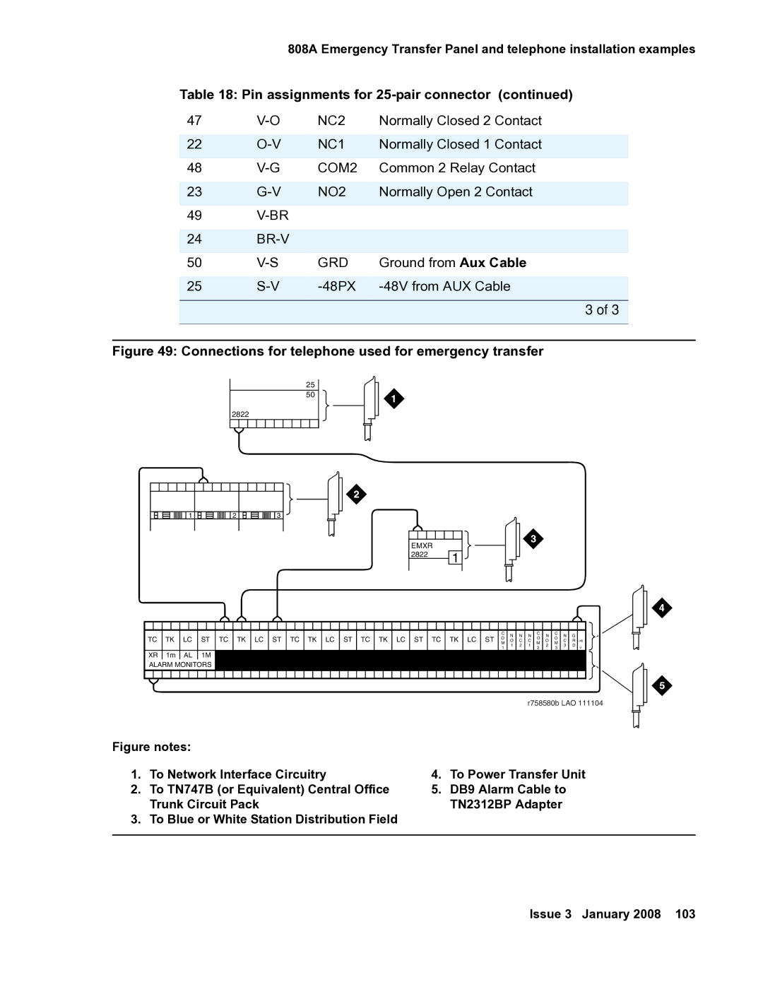
Figure 49: Connections for telephone used for emergency transfer
25
50
2822
![]() 1
1 ![]()
![]()
![]()
![]()
![]()
![]()
![]()
![]()
![]()
![]()
![]() 2
2 ![]()
![]()
![]()
![]()
![]()
![]()
![]()
![]()
![]()
![]()
![]() 3
3
EMXR |
|
2822 | 1 |
|
|
|
| C | N | N | N | C | N | C | N |
|
|
|
|
|
|
|
|
|
|
|
|
| ||||||||
|
|
|
|
|
|
|
| ||||||||
TC TK LC ST TC TK LC ST TC TK LC ST TC TK LC ST TC TK LC ST | G |
| |||||||||||||
O | O | O |
| ||||||||||||
M | O | C | C | M | O | M | C | R |
|
| |||||
|
|
| 1 | 2 | 1 | 2 | 3 | D |
|
| |||||
|
|
| 1 |
|
|
| 2 |
| 3 |
|
| V |
|
| |
XR 1m AL 1M | 3M 3m 3w |
|
|
|
|
|
|
|
|
|
|
|
|
| |
ALARM MONITORS |
|
|
|
|
|
|
|
|
|
|
|
|
|
|
|
|
|
|
|
|
|
|
|
|
|
|
|
|
|
| |
|
|
|
|
|
|
|
|
|
| ||||||
|
|
|
|
|
|
|
|
|
|
|
|
|
|
|
|
|
|
|
|
|
| r758580b LAO 111104 | |||||||||
Figure notes: |
|
| |
1. | To Network Interface Circuitry | 4. | To Power Transfer Unit |
2. | To TN747B (or Equivalent) Central Office | 5. | DB9 Alarm Cable to |
| Trunk Circuit Pack |
| TN2312BP Adapter |
3. | To Blue or White Station Distribution Field |
|
|
|
|
|
|